


Description
- description
- Downloads
- examples
- Projects
- Package Includes
Top Development Board :
- 16x2 Character LCD (standard driving interface & I2C capable).
- HC-05 Bluetooth module with level converter.
- ESP8266(ESP-01) Wi-Fi module.
- 3 x HC-SR04 Distance sensors for obstacle detection.
- MPU-9250 (gyroscope, accelerometer & compass) 9-axis motion processing Unit.
- MAX7219 compact, serial input/out-put common-cathode display driver.
- 4 Digit common cathode seven segment display.
- 5v Active buzzer with driver circuit.
- 2x optical encoders (125c51) for speed measurement.
- 6x IR Surrounding proximity sensors for obstacle detection.
- 8x Indicator LEDs.
- 8x line tracing indicator LEDs(configurable).
- 5x Push buttons for robot direction control (configurable).
- 4x servo motor plugin headers.
- Half breadboard (5.5 cm x 8.5 cm).
Bottom Development Board :
- 8bit (TCRT5000) Line following sensors.
- TP5100 Battery charging circuit.
- 2x 18650 4200mAH Battery.
- 4x TT130 Gear motors.
Top Development Board :
-
- Arduino Mega pro mini compatible. (pins are already connected to the platform).
- Any other controller board can be used when unplugged the Arduino Mega pro mini.
- LCD contrast adjust-ability.
- IR proximity sensitivity adjust-ability.
- Power rail: 5v & 3.3v.
- Robot platform accessibility.
Bottom Development Board (Robot Platform) :
- Common reset button.
- 8bit (TCRT5000) Line following sensors.
- TP5100 Battery charging circuit.
- 2x 18650 4200mAH Battery.
- 4x TT130 Gear motors.
- Line tracing sensors sensitivity adjust-ability.
- HC-05, HC-06 Bluetooth module plugin capability.
- HC-SR04 Ultrasonic module plugin capability.
- Exposed pins.
- The bottom platform can work alone (compatible with an Arduino Nano board ((pins are already connected to the motor driver, Bluetooth plugin header & Ultrasonic module plugin header)).
Other pins of the Arduino Nano are accessible via JTAG connector. - Motor driver power on/off switch.
- Caster wheel support.
- Product Dimensions : 200L x 160W x 80H mm.
- Net Weight : 720g.
- Gross weight : 1380g.
/*
INNOVATOR INTERNATIONAL (PVT)LTD.
https://www.innovator.lk/
-------------------------------------------------------------------
Development Platform : Dynamic 1.0
(mobile robot development platform)
-------------------------------------------------------------------
LEDs Example.
-------------------------------------------------------------------
Hardware setup :
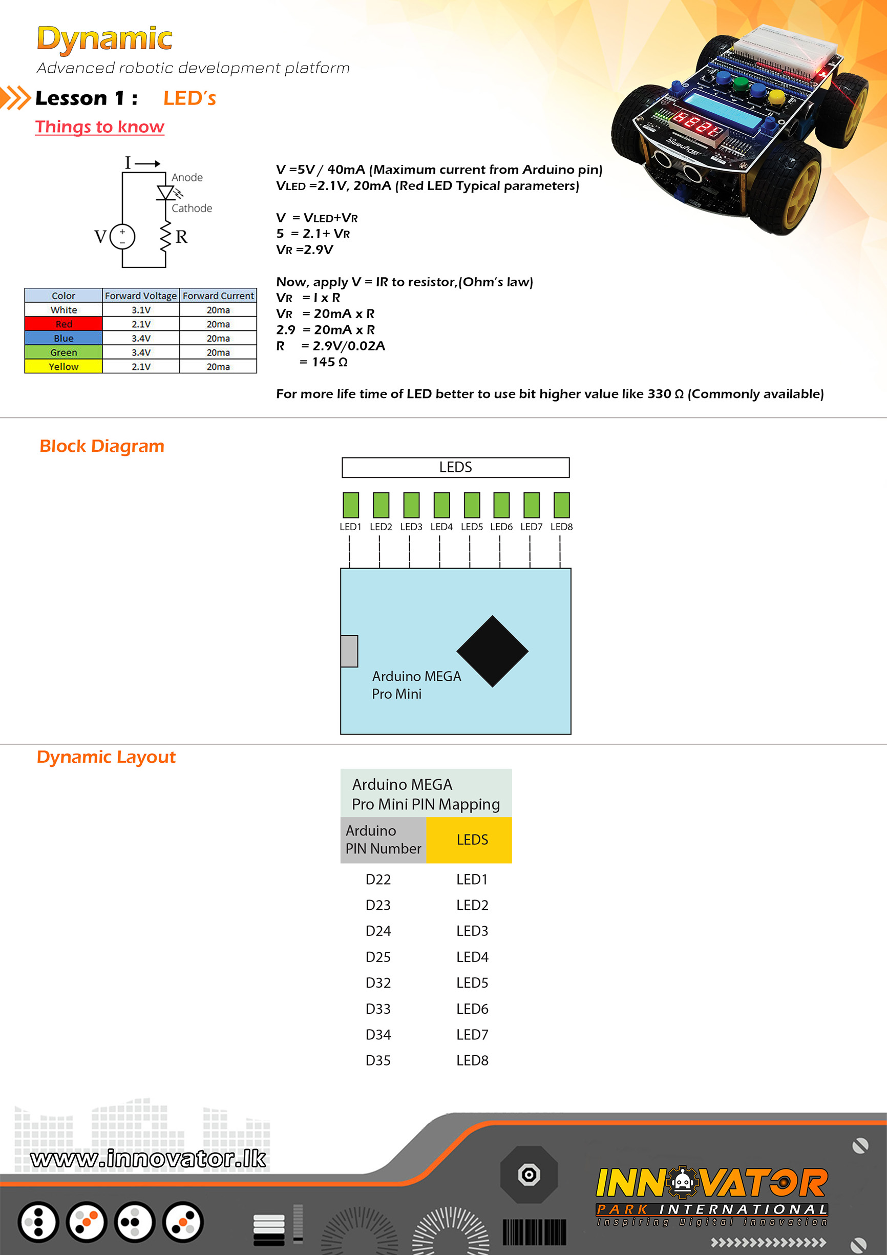
PINs of the LEDs(these LEDs are already connected and mapped)
LED 1 PIN connected to Arduino digital PIN -> 22(D22)
LED 2 PIN connected to Arduino digital PIN -> 23(D23)
LED 3 PIN connected to Arduino digital PIN -> 24(D24)
LED 4 PIN connected to Arduino digital PIN -> 25(D25)
LED 5 PIN connected to Arduino digital PIN -> 32(D32)
LED 6 PIN connected to Arduino digital PIN -> 33(D33)
LED 7 PIN connected to Arduino digital PIN -> 34(D34)
LED 8 PIN connected to Arduino digital PIN -> 35(D35)
-------------------------------------------------------------------
23 march 2021
*/
int LED1 = 22;// the number of the Arduino PIN, that LED 1 is connected to.
int LED2 = 23;// the number of the Arduino PIN, that LED 2 is connected to.
int LED3 = 24;// the number of the Arduino PIN, that LED 3 is connected to.
int LED4 = 25;// the number of the Arduino PIN, that LED 4 is connected to.
int LED5 = 32;// the number of the Arduino PIN, that LED 5 is connected to.
int LED6 = 33;// the number of the Arduino PIN, that LED 6 is connected to.
int LED7 = 34;// the number of the Arduino PIN, that LED 7 is connected to.
int LED8 = 35;// the number of the Arduino PIN, that LED 8 is connected to.
void setup() {
//making all LED PINs as outputs.
pinMode(LED1, OUTPUT);
pinMode(LED2, OUTPUT);
pinMode(LED3, OUTPUT);
pinMode(LED4, OUTPUT);
pinMode(LED5, OUTPUT);
pinMode(LED6, OUTPUT);
pinMode(LED7, OUTPUT);
pinMode(LED8, OUTPUT);
}
void loop() {
digitalWrite(LED1, HIGH);
digitalWrite(LED2, HIGH);
digitalWrite(LED3, HIGH);
digitalWrite(LED4, HIGH);
digitalWrite(LED5, HIGH);
digitalWrite(LED6, HIGH);
digitalWrite(LED7, HIGH);
digitalWrite(LED8, HIGH);
delay(1000);
digitalWrite(LED1, LOW);
digitalWrite(LED2, LOW);
digitalWrite(LED3, LOW);
digitalWrite(LED4, LOW);
digitalWrite(LED5, LOW);
digitalWrite(LED6, LOW);
digitalWrite(LED7, LOW);
digitalWrite(LED8, LOW);
delay(1000);
}
/*
INNOVATOR INTERNATIONAL (PVT)LTD.
https://www.innovator.lk/
--------------------------------------------------------
Development Platform : Dynamic 1.0
(mobile robot development platform)
--------------------------------------------------------
Buttons Example.
--------------------------------------------------------
Hardware setup :
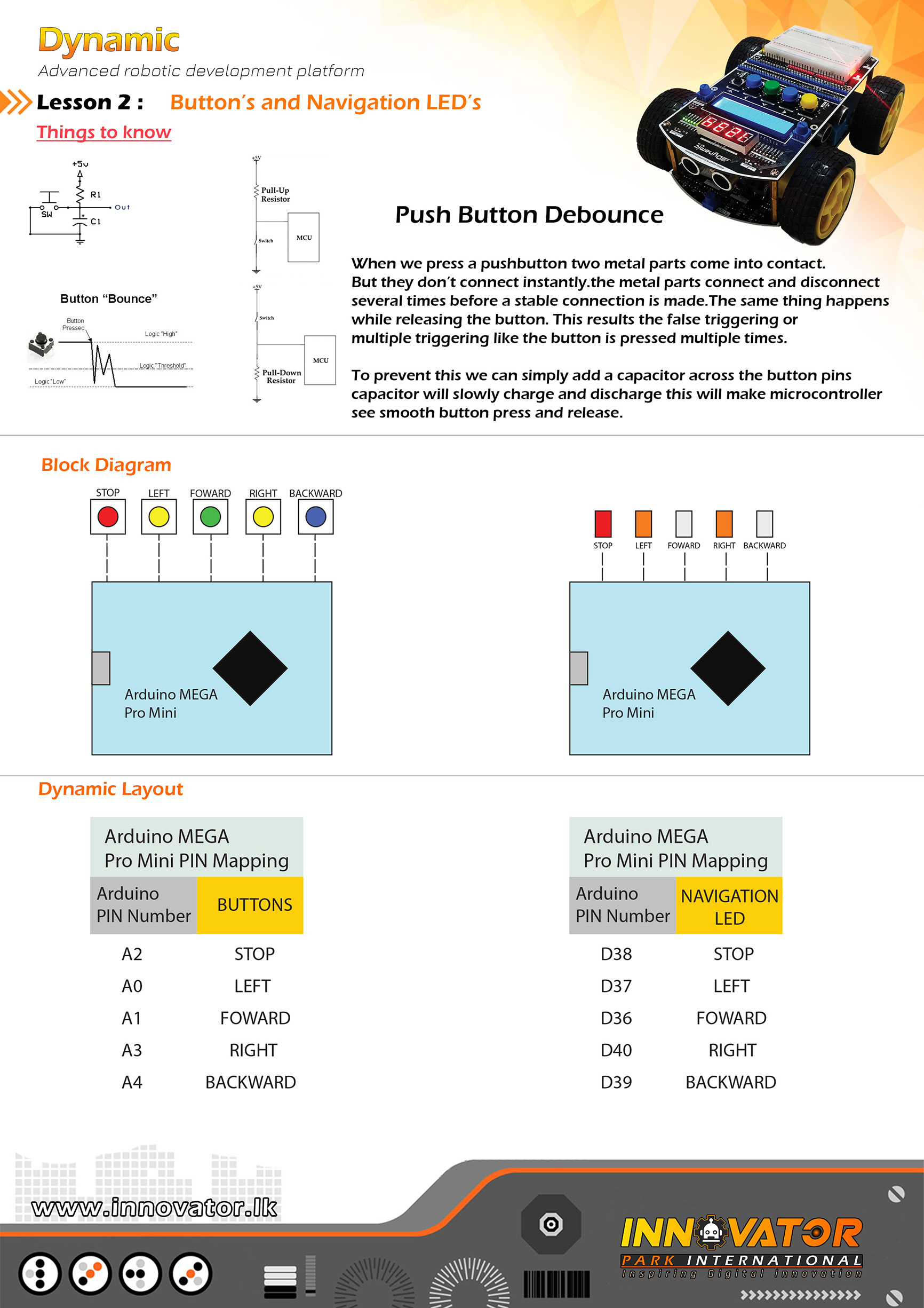
Buttons and button press indicator LEDs are all ready
mapped and connected to the Arduino board.
PINs are as follows :
--------------------------------------------------------
Buttons:
BACKWARD button : PIN -> Arduino analog PIN 4(A4)
RIGHT button : PIN -> Arduino analog PIN 3(A3)
FORWARD button : PIN -> Arduino analog PIN 1(A1)
LEFT button : PIN -> Arduino analog PIN 0(A0)
STOP button : PIN -> Arduino analog PIN 2(A2)
--------------------------------------------------------
LEDs:
BACKWARD LED : PIN -> Arduino digital PIN 39(D39)
RIGHT LED : PIN -> Arduino digital PIN 40(D40)
FORWARD LED : PIN -> Arduino digital PIN 36(D36)
LEFT LED : PIN -> Arduino digital PIN 37(D37)
STOP LED : PIN -> Arduino digital PIN 38(D38)
--------------------------------------------------------
23 march 2021
*/
//------------------------------BUTTON PINs----------------------------------------------------
int BUTTON_LEFT = A0;// the number of the Arduino PIN, that left button is connected to.
int BUTTON_RIGHT = A3;// the number of the Arduino PIN, that right button is connected to.
int BUTTON_FORWARD = A1;// the number of the Arduino PIN, that forward button is connected to.
int BUTTON_BACK = A4;// the number of the Arduino PIN, that backward button is connected to.
int BUTTON_STOP = A2;// the number of the Arduino PIN, that stop button is connected to.
//------------------------------LED PINs-------------------------------------------------------
int LED_LEFT = 37;// the number of the Arduino PIN, that left LED is connected to.
int LED_RIGHT = 40;// the number of the Arduino PIN, that right LED is connected to.
int LED_FORWARD = 36;// the number of the Arduino PIN, that forward LED is connected to.
int LED_BACK = 39;// the number of the Arduino PIN, that backward LED is connected to.
int LED_STOP = 38;// the number of the Arduino PIN, that stop LED is connected to.
void setup() {
//initializing all button PINs as inputs.
pinMode(BUTTON_LEFT, INPUT);
pinMode(BUTTON_RIGHT, INPUT);
pinMode(BUTTON_FORWARD, INPUT);
pinMode(BUTTON_BACK, INPUT);
pinMode(BUTTON_STOP, INPUT);
//initializing all LED PINs as outputs.
pinMode(LED_LEFT, OUTPUT);
pinMode(LED_FORWARD, OUTPUT);
pinMode(LED_RIGHT, OUTPUT);
pinMode(LED_STOP, OUTPUT);
pinMode(LED_BACK, OUTPUT);
}
void loop() {
//digital read each button and check if the value is equal to zero.
if (digitalRead(BUTTON_LEFT) == 0) {//if the button is pressed, the value will be zero
digitalWrite(LED_LEFT, HIGH);//if value is zero turn the Corresponding LED on.
} else {
digitalWrite(LED_LEFT, LOW);//else turn off the LED.
}
if (digitalRead(BUTTON_RIGHT) == 0) {//if the button is pressed, the value will be zero
digitalWrite(LED_RIGHT, HIGH);//if value is zero turn the Corresponding LED on.
} else {
digitalWrite(LED_RIGHT, LOW);//else turn off the LED.
}
if (digitalRead(BUTTON_FORWARD) == 0) {//if the button is pressed, the value will be zero
digitalWrite(LED_FORWARD, HIGH);//if value is zero turn the Corresponding LED on.
} else {
digitalWrite(LED_FORWARD, LOW);//else turn off the LED.
}
if (digitalRead(BUTTON_BACK) == 0) {//if the button is pressed, the value will be zero
digitalWrite(LED_BACK, HIGH);//if value is zero turn the Corresponding LED on.
} else {
digitalWrite(LED_BACK, LOW);//else turn off the LED.
}
if (digitalRead(BUTTON_STOP) == 0) {//if the button is pressed, the value will be zero
digitalWrite(LED_STOP, HIGH);//if value is zero turn the Corresponding LED on.
} else {
digitalWrite(LED_STOP, LOW);//else turn off the LED.
}
}
/*
INNOVATOR INTERNATIONAL (PVT)LTD.
https://www.innovator.lk/
----------------------------------------------------------------------------
Development Platform : Dynamic 1.0
(mobile robot development platform)
----------------------------------------------------------------------------
Buzzer Example.
----------------------------------------------------------------------------
Hardware setup :
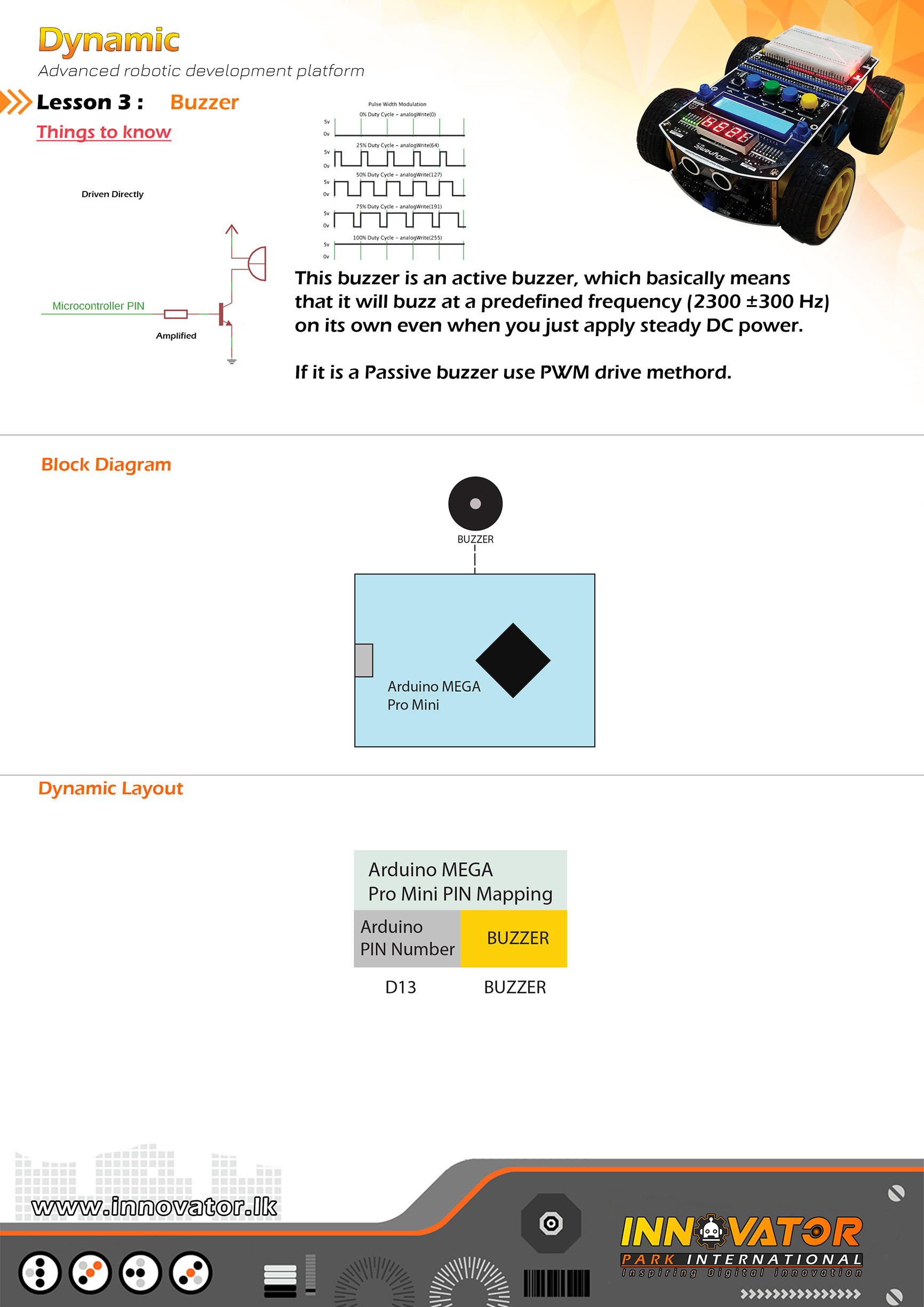
Buzzer PIN already mapped and connected to Arduino digital PIN -> 13(D13)
----------------------------------------------------------------------------
23 march 2021
*/
int Buz = 13;// the number of the buzzer PIN.
void setup() {
pinMode(Buz, OUTPUT);//initializing Buz pin as a output pin.
}
void loop() {
digitalWrite(Buz, HIGH);//turning on the buzzer.
delay(1000);//waiting one second to be elapsed.
digitalWrite(Buz, LOW);//turning off the buzzer.
delay(1000);//waiting one second to be elapsed.
}
/*
INNOVATOR INTERNATIONAL (PVT)LTD.
https://www.innovator.lk/
----------------------------------------------------------------------------
Development Platform : Dynamic 1.0
(mobile robot development platform)
----------------------------------------------------------------------------
IR Proximity Example.
----------------------------------------------------------------------------
Hardware setup :
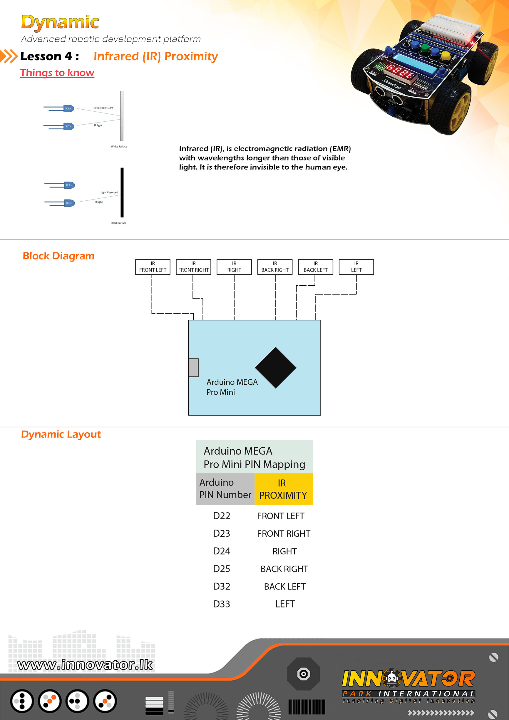
PINs of the IR Sensor's mounted around the top development board are
already mapped and connected.PINs are as follows :
IR FRONT LEFT : Arduino digital PIN -> 49(D49)
IR FRONT RIGHT : Arduino digital PIN -> 50(D50)
IR RIGHT : Arduino digital PIN -> 48(D48)
IR BACK RIGHT : Arduino digital PIN -> 47(D47)
IR BACK LEFT : Arduino digital PIN -> 42(D42)
IR LEFT : Arduino digital PIN -> 41(D41)
----------------------------------------------------------------------------
23 march 2021
*/
int IR_FRONT_LEFT = 49;// the number of the Arduino PIN, that front left IR sensor is connected to.
int IR_FRONT_RIGHT = 50;// the number of the Arduino PIN, that front right IR sensor is connected to.
int IR_LEFT = 48;// the number of the Arduino PIN, that left IR sensor is connected to.
int IR_RIGHT = 47;// the number of the Arduino PIN, that right IR sensor is connected to.
int IR_BACK_LEFT = 42;// the number of the Arduino PIN, that back left IR sensor is connected to.
int IR_BACK_RIGHT = 41;// the number of the Arduino PIN, that back right IR sensor is connected to.
int s1, s2, s3, s4, s5, s6; //creating variables to hold ir sensor readings.
void setup() {
Serial.begin(9600); //starting serial communication between arduino and computer.
}
void loop() {
//reading and printing each sensors value in to the serial monitor
s1 = digitalRead(IR_FRONT_LEFT);
Serial.print(s1);
Serial.print("t");
s2 = digitalRead(IR_FRONT_RIGHT);
Serial.print(s2);
Serial.print("t");
s3 = digitalRead(IR_LEFT);
Serial.print(s3);
Serial.print("t");
s4 = digitalRead(IR_RIGHT);
Serial.print(s4);
Serial.print("t");
s5 = digitalRead(IR_BACK_LEFT);
Serial.print(s5);
Serial.print("t");
s6 = digitalRead(IR_BACK_RIGHT);
Serial.print(s6);
Serial.print("t");
Serial.println("end");
}
/*
INNOVATOR INTERNATIONAL (PVT)LTD.
https://www.innovator.lk/
--------------------------------------------------------
Development Platform : Dynamic 1.0
(mobile robot development platform)
--------------------------------------------------------
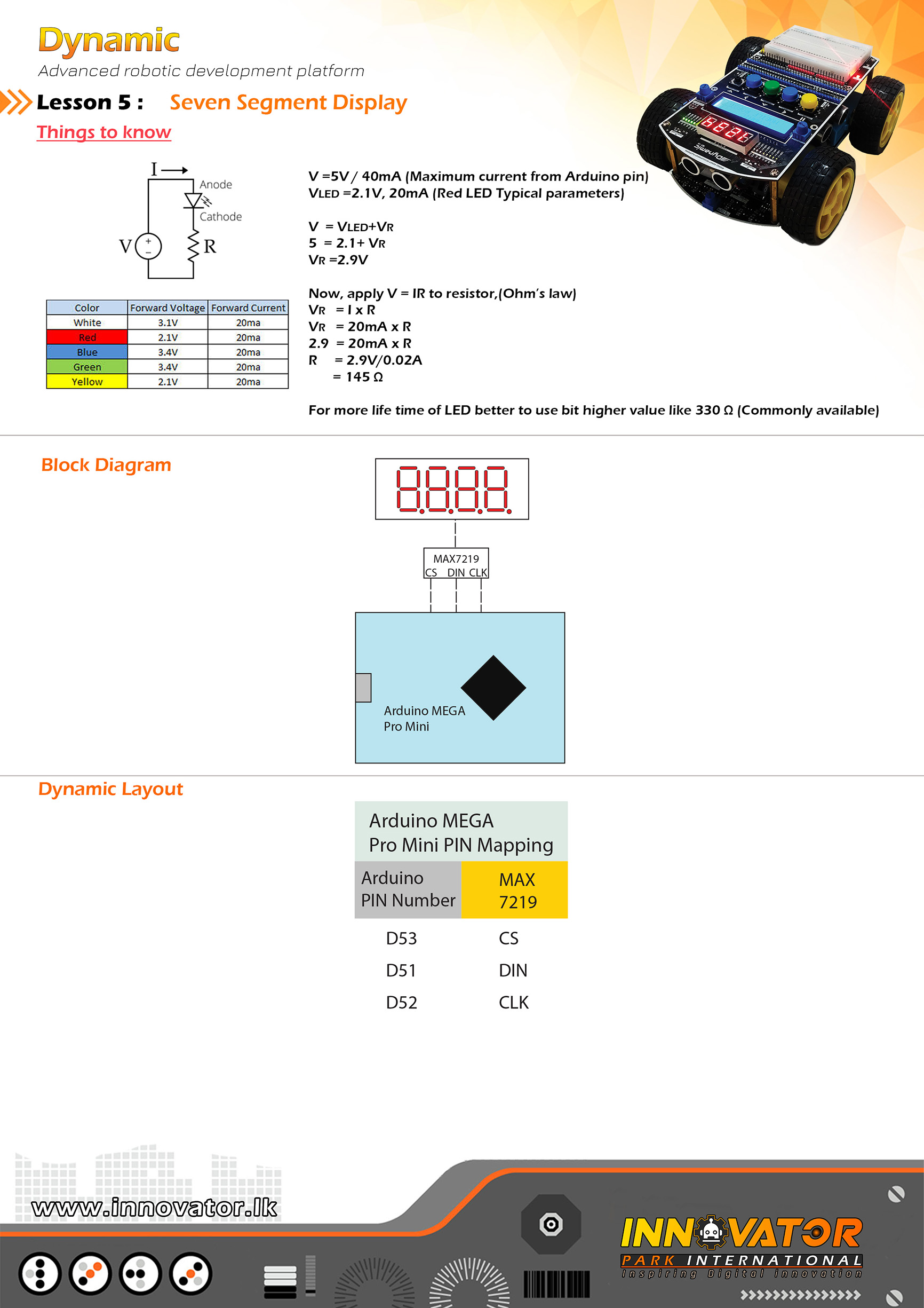
Seven Segment Example.
--------------------------------------------------------
Hardware setup :
Seven Segment Display Driver(7219) PINs are allready
mapped and connected to the Arduino board.
PINs are as follows :
--------------------------------------------------------
DIN connected to Arduino digital PIN -> 51
CS connected to Arduino digital PIN -> 52
CLK connected to Arduino digital PIN -> 53
--------------------------------------------------------
23 march 2021
*/
int DIN = 51;
int CLK = 52;
int CS = 53;
#include "LedControl.h"
LedControl lc = LedControl(DIN, CLK, CS, 1);
void setup() {
lc.shutdown(0, false);//The MAX7219 is in power-saving mode on startup,so we do a wakeup call.
lc.setIntensity(0, 15);//setting the display brightness to its maximum.(brightness : 0 t0 15).
lc.clearDisplay(0);//clearing the display.
//sending data to display.
lc.setDigit(0, 3, 1, false);
lc.setDigit(0, 2, 2, true);
lc.setDigit(0, 1, 3, true);
lc.setDigit(0, 0, 4, false);
}
void loop() {
}
/*
INNOVATOR INTERNATIONAL (PVT)LTD.
https://www.innovator.lk/
------------------------------------------------------------------
Development Platform : Dynamic 1.0
(mobile robot development platform)
------------------------------------------------------------------
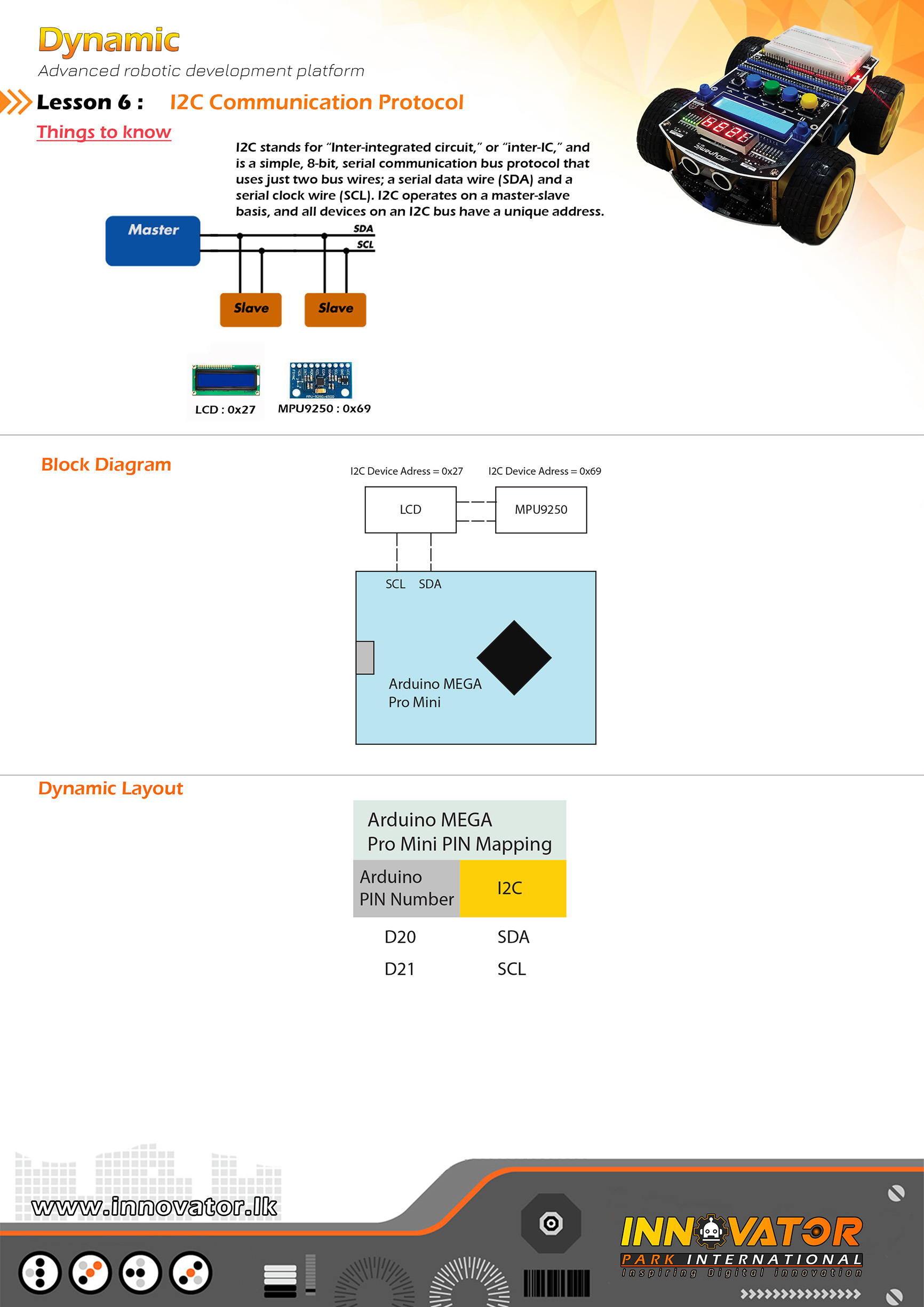
I2C Device Scanning Example.
------------------------------------------------------------------
Hardware setup :
All intergrated I2C devices are is allready mapped and connected
to the Arduino board.
------------------------------------------------------------------
I2C device at address 0x27 = 16*2 LCD
I2C device at address 0x69 = MPU9250
------------------------------------------------------------------
22 march 2021
*/
#include "Wire.h" //including the wire library in order to communicate with i2c bus devices.
void setup()
{
Wire.begin(); //initializing connection to the i2c device(s).
Serial.begin(9600);//starting serial communication between arduino and computer.
Serial.println("nI2C Scanner");//printing message to serial monitor.
}
void loop()
{
byte error, address; //variables to hold the error values and i2c devices addresses.
int nDevices;//a variable to hold the i2c device count.
Serial.println("Scanning...");//printing message to serial monitor.
nDevices = 0;
for (address = 1; address < 127; address++ )
{
// the i2c_scanner uses the return value of
// the Write.endTransmisstion to see if
// a device did acknowledge to the address.
Wire.beginTransmission(address);
error = Wire.endTransmission();
if (error == 0)
{
Serial.print("I2C device found at address 0x");
if (address < 16)
Serial.print("0");
Serial.print(address, HEX);
Serial.println(" !");
nDevices++;
}
else if (error == 4)
{
Serial.print("Unknown error at address 0x");
if (address < 16)
Serial.print("0");
Serial.println(address, HEX);
}
}
if (nDevices == 0)
Serial.println("No I2C devices foundn");
else
Serial.println("donen");
delay(5000);// wait 5 seconds between each next scan.
}
/*
INNOVATOR INTERNATIONAL (PVT)LTD.
https://www.innovator.lk/
----------------------------------------------------------------------------
Development Platform : Dynamic 1.0
(mobile robot development platform)
----------------------------------------------------------------------------
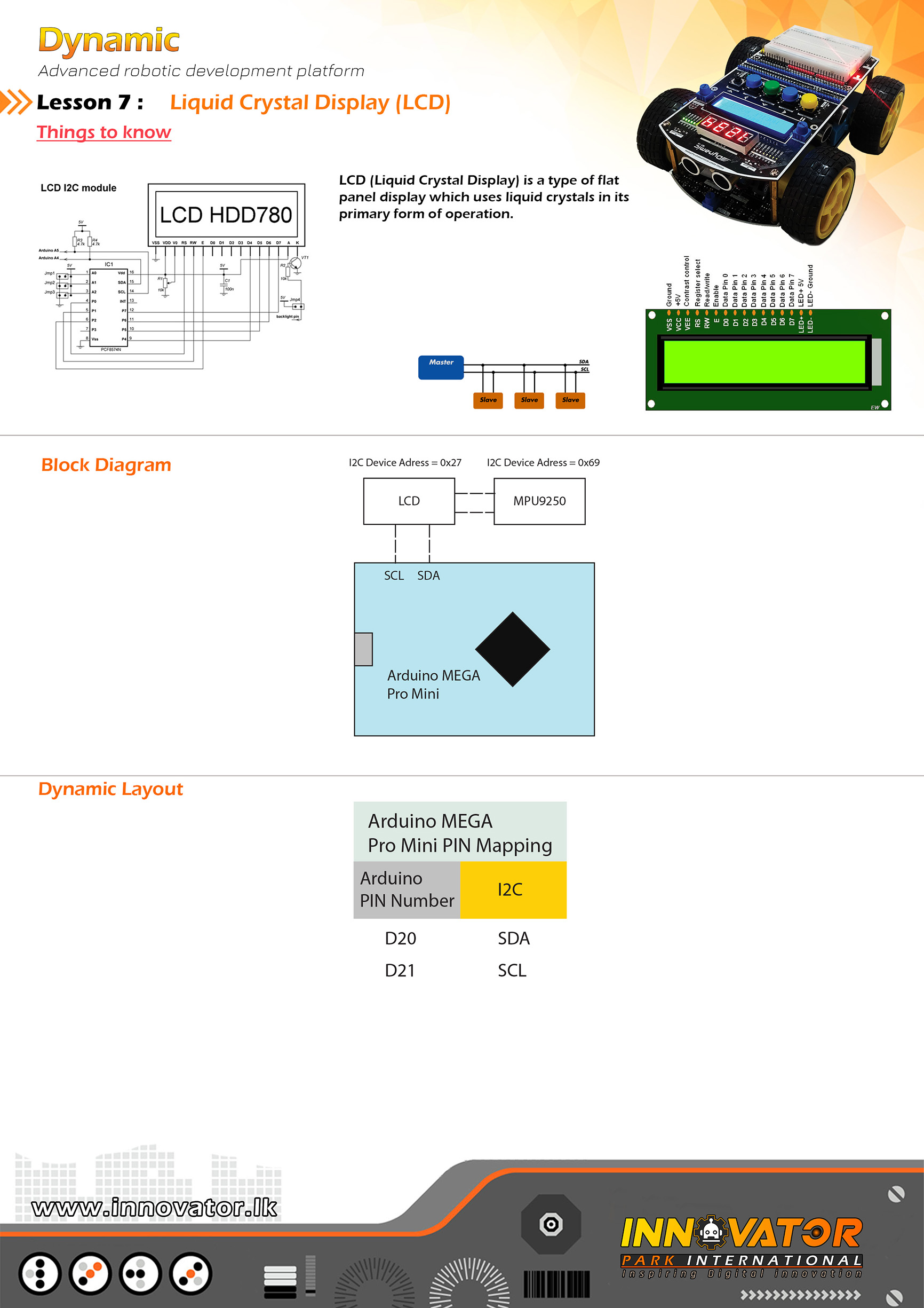
HD44780 16*2 LCD Example.
----------------------------------------------------------------------------
Hardware setup :
16*2 LCD is all ready connected to the Arduino board.
LCD's I2C address is 0x27.
----------------------------------------------------------------------------
23 march 2021
*/
#include "LiquidCrystal_I2C.h"//including the LCD driver library.
LiquidCrystal_I2C lcd(0x27, 16, 2);//initializing the LCD I2C address(0x27) and LCD's number of columns(16) and rows(2).
void setup() {
lcd.begin();//initializing connection to the LCD.
lcd.backlight();//turning on the backlight of the LCD.
lcd.setCursor(0, 0);//setting the cursor position to column 0 and row 0.
lcd.print("Dynamic");//printing a message to LCD.
delay(1000);//waiting for one second to be elapsed.
lcd.clear();//clearing the charcters printedd on the LCD.
}
void loop() {
lcd.setCursor(2, 0);//setting the cursor position to column 2 and row 0.
lcd.print("Hello world !");//printing a message to LCD.
}
/*
INNOVATOR INTERNATIONAL (PVT)LTD.
https://www.innovator.lk/
--------------------------------------------------------
Development Platform : Dynamic 1.0
(mobile robot development platform)
--------------------------------------------------------
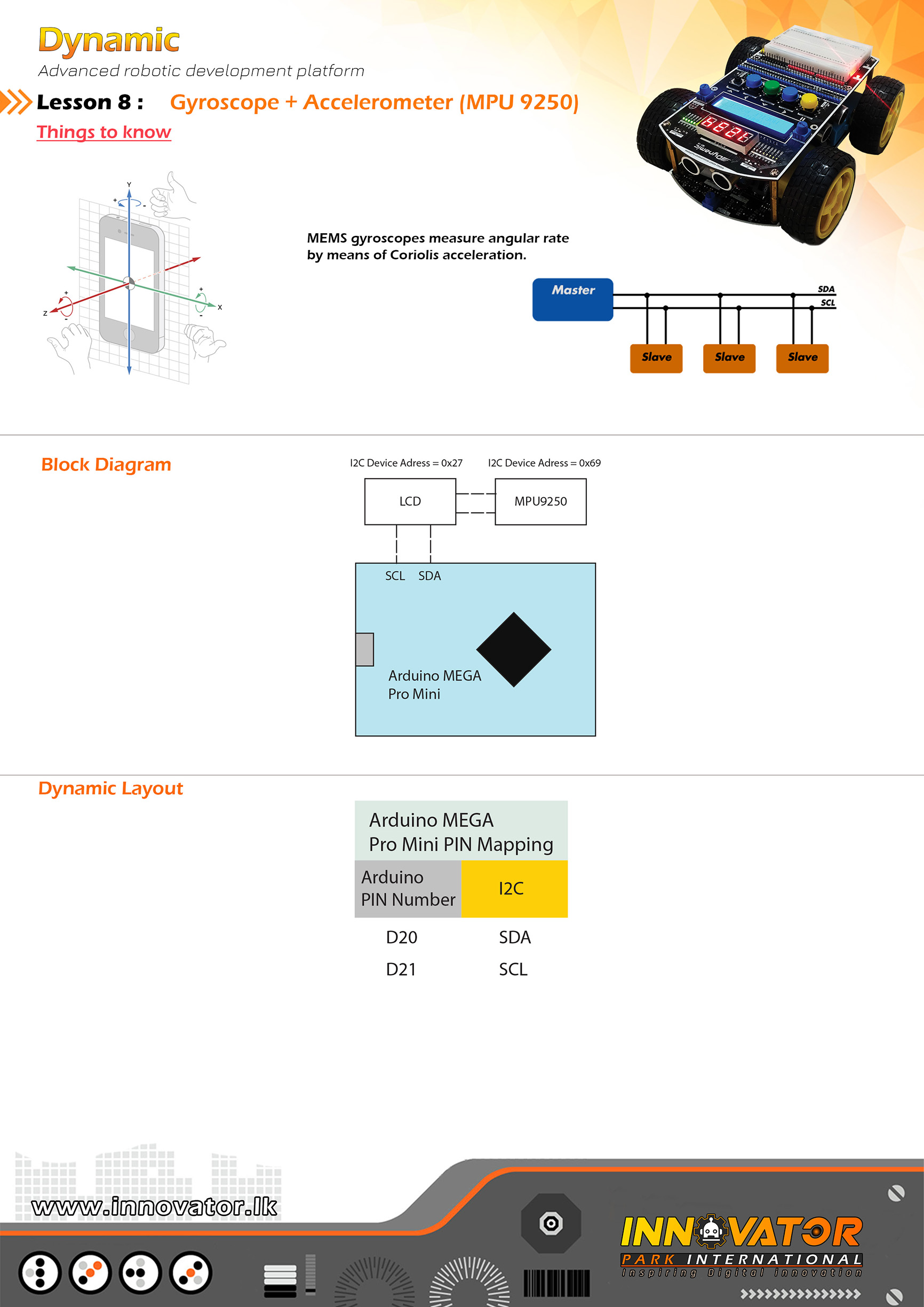
MPU9050 Example.
--------------------------------------------------------
Hardware setup :
MPU9050 is allready mapped and connected to the
Arduino board.I2C address is : 0x69
--------------------------------------------------------
23 march 2021
*/
#include "Wire.h"//including wire library, in order to communicate with I2C devices.
int MPU9250_ADDRESS = 0x69;//MPU9250 module's i2c address.
int MAG_ADDRESS = 0x0C;//MPU9250 module's magnetometer i2c address.
int GYRO_FULL_SCALE_250_DPS = 0x00;
int GYRO_FULL_SCALE_500_DPS = 0x08;
int GYRO_FULL_SCALE_1000_DPS = 0x10;
int GYRO_FULL_SCALE_2000_DPS = 0x18;
int ACC_FULL_SCALE_2_G = 0x00;
int ACC_FULL_SCALE_4_G = 0x08;
int ACC_FULL_SCALE_8_G = 0x10;
int ACC_FULL_SCALE_16_G = 0x18;
// This function read Nbytes bytes from I2C device at address Address.
// Put read bytes starting at register Register in the Data array.
long int ti;
void setup()
{
Wire.begin();
Serial.begin(9600);
// Set accelerometers low pass filter at 5Hz
I2CwriteByte(MPU9250_ADDRESS, 29, 0x06);
// Set gyroscope low pass filter at 5Hz
I2CwriteByte(MPU9250_ADDRESS, 26, 0x06);
// Configure gyroscope range
I2CwriteByte(MPU9250_ADDRESS, 27, GYRO_FULL_SCALE_1000_DPS);
// Configure accelerometers range
I2CwriteByte(MPU9250_ADDRESS, 28, ACC_FULL_SCALE_4_G);
// Set by pass mode for the magnetometers
I2CwriteByte(MPU9250_ADDRESS, 0x37, 0x02);
// Request continuous magnetometer measurements in 16 bits
I2CwriteByte(MAG_ADDRESS, 0x0A, 0x16);
// Store initial time
ti = millis();
}
// Counter
long int cpt = 0;
// Main loop, read and display data
void loop()
{
// Display time
Serial.print (millis() - ti, DEC);
Serial.print ("t");
// ____________________________________
// ::: accelerometer and gyroscope :::
// Read accelerometer and gyroscope
uint8_t Buf[14];
I2Cread(MPU9250_ADDRESS, 0x3B, 14, Buf);
// Create 16 bits values from 8 bits data
// Accelerometer
int16_t ax = -(Buf[0] << 8 | Buf[1]);
int16_t ay = -(Buf[2] << 8 | Buf[3]);
int16_t az = Buf[4] << 8 | Buf[5];
// Gyroscope
int16_t gx = -(Buf[8] << 8 | Buf[9]);
int16_t gy = -(Buf[10] << 8 | Buf[11]);
int16_t gz = Buf[12] << 8 | Buf[13];
//printing accelerometer values to serial monitor.
Serial.print (ax, DEC);
Serial.print ("t");
Serial.print (ay, DEC);
Serial.print ("t");
Serial.print (az, DEC);
Serial.print ("t");
//printing gyroscope values to serial monitor.
Serial.print (gx, DEC);
Serial.print ("t");
Serial.print (gy, DEC);
Serial.print ("t");
Serial.print (gz, DEC);
Serial.print ("t");
//-----------------------------------------------
//reading magnetometer values.
//waiting data to be ready.
uint8_t ST1;
do
{
I2Cread(MAG_ADDRESS, 0x02, 1, &ST1);
}
while (!(ST1 & 0x01));
//reading magnetometer data.
uint8_t Mag[7];
I2Cread(MAG_ADDRESS, 0x03, 7, Mag);
// Create 16 bits values from 8 bits data
// Magnetometer
int16_t mx = -(Mag[3] << 8 | Mag[2]);
int16_t my = -(Mag[1] << 8 | Mag[0]);
int16_t mz = -(Mag[5] << 8 | Mag[4]);
//printing magnetometer values to serial monitor.
Serial.print (mx + 200, DEC);
Serial.print ("t");
Serial.print (my - 70, DEC);
Serial.print ("t");
Serial.print (mz - 700, DEC);
Serial.print ("t");
Serial.println("");
}
void I2Cread(uint8_t Address, uint8_t Register, uint8_t Nbytes, uint8_t* Data)
{
// Set register address
Wire.beginTransmission(Address);
Wire.write(Register);
Wire.endTransmission();
// Read Nbytes
Wire.requestFrom(Address, Nbytes);
uint8_t index = 0;
while (Wire.available())
Data[index++] = Wire.read();
}
// Write a byte (Data) in device (Address) at register (Register)
void I2CwriteByte(uint8_t Address, uint8_t Register, uint8_t Data)
{
// Set register address
Wire.beginTransmission(Address);
Wire.write(Register);
Wire.write(Data);
Wire.endTransmission();
}
/*
INNOVATOR INTERNATIONAL (PVT)LTD.
https://www.innovator.lk/
-----------------------------------------------------------------
Development Platform : Dynamic 1.0
(mobile robot development platform)
-----------------------------------------------------------------
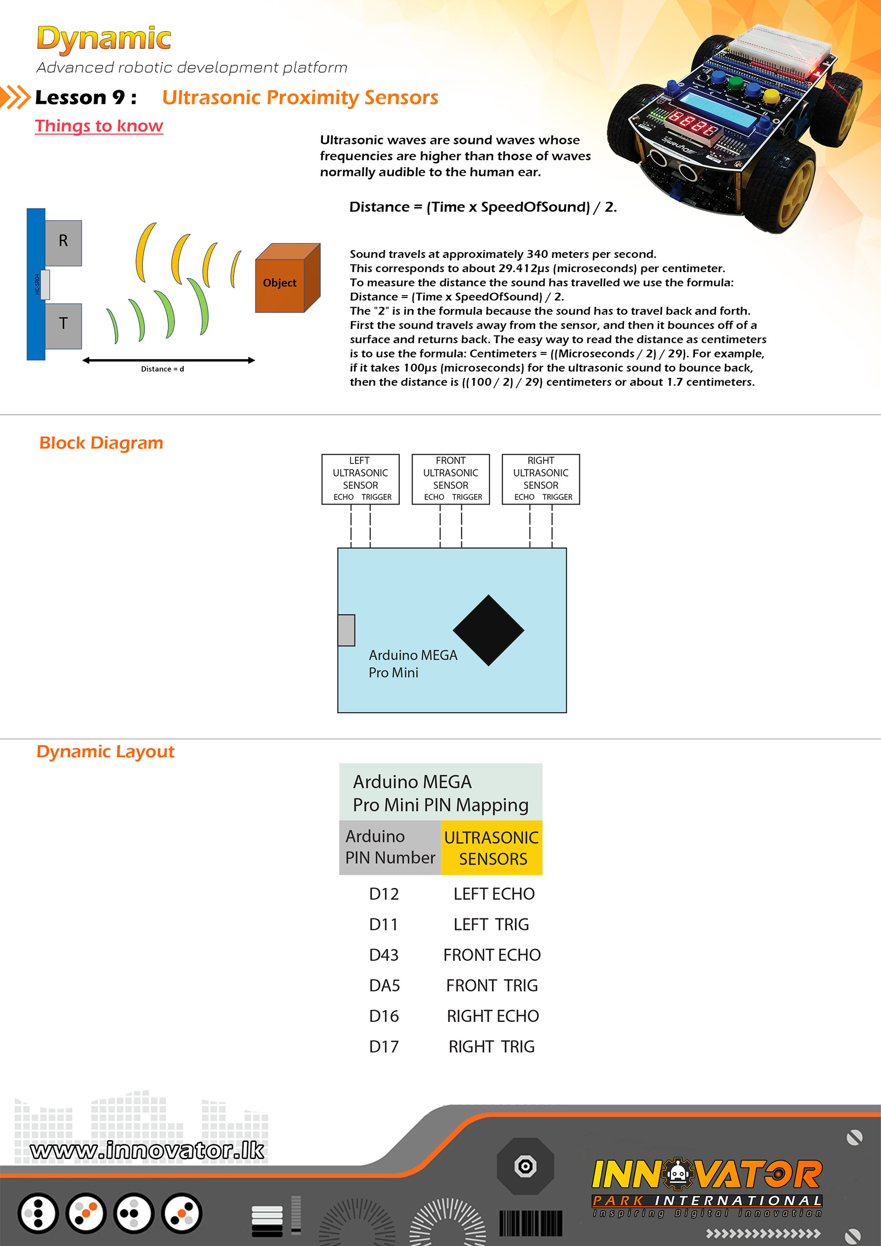
hc-sr04 Ultrasonic Distance Sensor Example.
-----------------------------------------------------------------
Hardware setup :
PINS of the ultrasonic sensors are already mapped and
connected.PINs are as follows :
front ultrasonic sensor TRIG PIN -> Arduino analog PIN 5(A5)
front ultrasonic sensor ECHO PIN -> Arduino analog PIN 43(D43)
left ultrasonic sensor TRIG PIN -> Arduino analog PIN 11(D11)
left ultrasonic sensor ECHO PIN -> Arduino analog PIN 12(D12)
right ultrasonic sensor TRIG PIN -> Arduino analog PIN 17(D17)
right ultrasonic sensor ECHO PIN -> Arduino analog PIN 16(D16)
-----------------------------------------------------------------
23 march 2021
*/
const int FRONT_TRIG_PIN = A5; // the number of the PIN, that front ultrasonic sensor's trigger PIN is connected to.
const int FRONT_ECHO_PIN = 43;// the number of the PIN, that front ultrasonic sensor's echo PIN is connected to.
const int LEFT_TRIG_PIN = 11;// the number of the PIN, that left ultrasonic sensor's trigger PIN is connected to.
const int LEFT_ECHO_PIN = 12;// the number of the PIN, that left ultrasonic sensor's echo PIN is connected to.
const int RIGHT_TRIG_PIN = 17;// the number of the PIN, that right ultrasonic sensor's trigger PIN is connected to.
const int RIGHT_ECHO_PIN = 16;// the number of the PIN, that right ultrasonic sensor's echo PIN is connected to.
long FRONT_DURATION;//variable to store the duration.
int FRONT_DISTANCE;//variable to store the duration.
long LEFT_DURATION;//variable to store the duration.
int LEFT_DISTANCE;//variable to store the duration.
long RIGHT_DURATION;//variable to store the duration.
int RIGHT_DISTANCE;//variable to store the duration.
void setup() {
//initializing all TRIG PINs as outputs.
pinMode(FRONT_TRIG_PIN, OUTPUT);
pinMode(LEFT_TRIG_PIN, OUTPUT);
pinMode(RIGHT_TRIG_PIN, OUTPUT);
//initializing all ECHO PINs as outputs.
pinMode(FRONT_ECHO_PIN, INPUT);
pinMode(LEFT_ECHO_PIN, INPUT);
pinMode(RIGHT_ECHO_PIN, INPUT);
Serial.begin(9600);//starting serial communication between arduino and computer.
}
void loop() {
//-------------------------front ultrasonic sensor------------------------------
digitalWrite(FRONT_TRIG_PIN, LOW);//turning off the trigger if its already on.
delayMicroseconds(2);//waiting for two microseconds.
digitalWrite(FRONT_TRIG_PIN, HIGH);//turning on the trigger.
delayMicroseconds(10);//waiting for ten microseconds.
digitalWrite(FRONT_TRIG_PIN, LOW);//turning off the trigger.
//doing the calculations
FRONT_DURATION = pulseIn(FRONT_ECHO_PIN, HIGH);
FRONT_DISTANCE = FRONT_DURATION * 0.034 / 2;
//printing calculations to the serial monitor.
Serial.print("FRONT_DISTANCE: ");
Serial.print(FRONT_DISTANCE);
//-------------------------left ultrasonic sensor------------------------------
digitalWrite(LEFT_TRIG_PIN, LOW);//turning off the trigger if its already on.
delayMicroseconds(2);//waiting for two microseconds.
digitalWrite(LEFT_TRIG_PIN, HIGH);//turning on the trigger.
delayMicroseconds(10);//waiting for ten microseconds.
digitalWrite(LEFT_TRIG_PIN, LOW);//turning off the trigger.
//doing the calculations
LEFT_DURATION = pulseIn(LEFT_ECHO_PIN, HIGH);
LEFT_DISTANCE = LEFT_DURATION * 0.034 / 2;
//printing calculations to the serial monitor.
Serial.print(" LEFT_DISTANCE: ");
Serial.print(LEFT_DISTANCE);
//-------------------------right ultrasonic sensor------------------------------
digitalWrite(RIGHT_TRIG_PIN, LOW);//turning off the trigger if its already on.
delayMicroseconds(2);//waiting for two microseconds.
digitalWrite(RIGHT_TRIG_PIN, HIGH);//turning on the trigger.
delayMicroseconds(10);//waiting for ten microseconds.
digitalWrite(RIGHT_TRIG_PIN, LOW);//turning off the trigger.
//doing the calculations
RIGHT_DURATION = pulseIn(RIGHT_ECHO_PIN, HIGH);
RIGHT_DISTANCE = RIGHT_DURATION * 0.034 / 2;
//printing calculations to the serial monitor.
Serial.print(" RIGHT_DISTANCE: ");
Serial.println(RIGHT_DISTANCE);
}
/*
INNOVATOR INTERNATIONAL (PVT)LTD.
https://www.innovator.lk/
--------------------------------------------------------
Development Platform : Dynamic 1.0
(mobile robot development platform)
--------------------------------------------------------
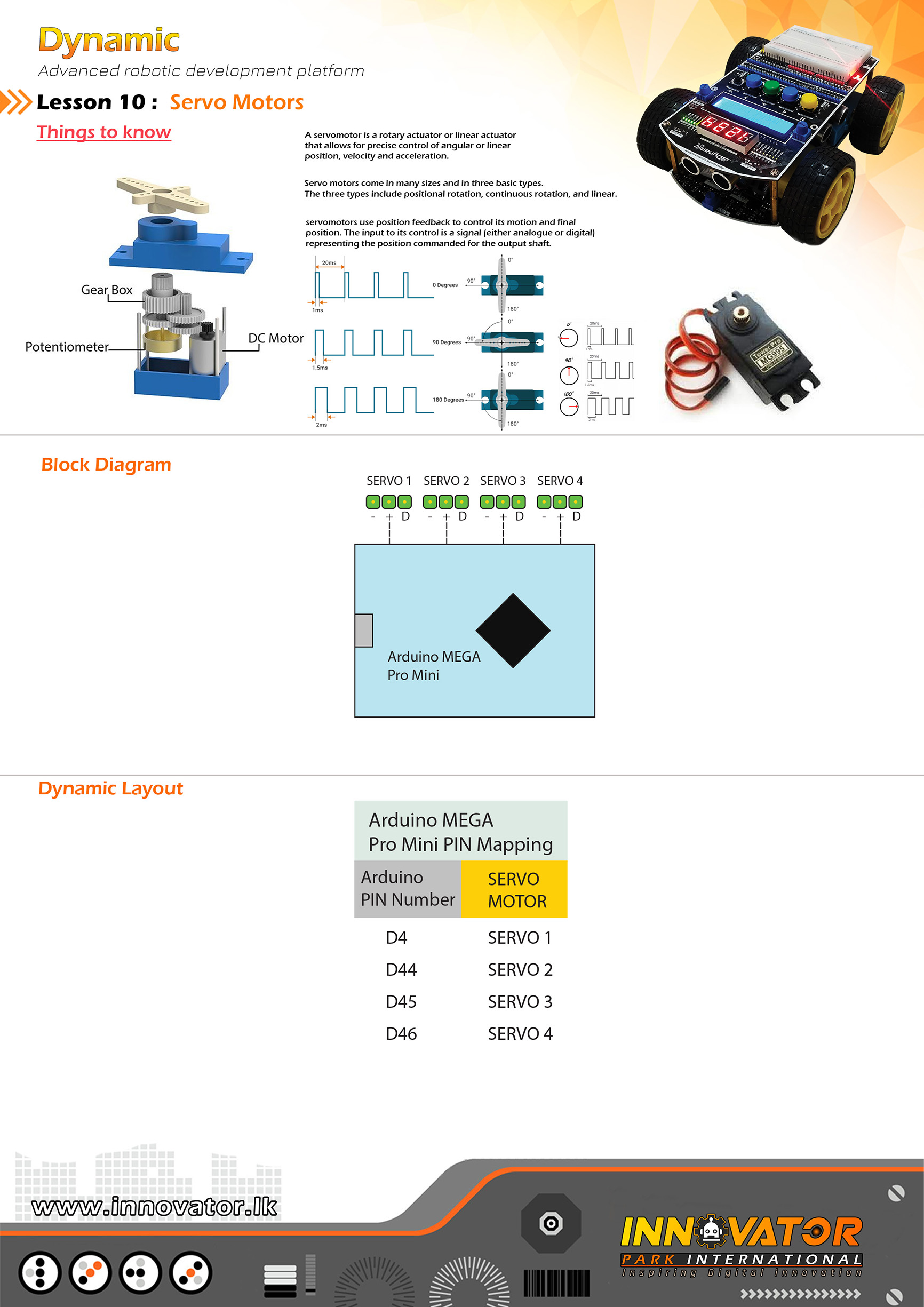
Servo Motor Example.
--------------------------------------------------------
Hardware setup :
Connect servo motors to "SERVO MOTORs" PINs located on
top development board.
--------------------------------------------------------
SG90 servo motor PIN outs :
//orange = pwm
//red = 5v
//brown = gnd
--------------------------------------------------------
23 march 2021
*/
#include "Servo.h" //including the servo library in order to use its functions.
// set the number of servo motors.
#define SERVOS 4
// creating the servo object to control a servo motor(s).
Servo myservo[SERVOS];
// attach servo motor(s) to digital PIN on the Arduino.
int servo_pins[SERVOS] = {4, 44, 45, 46}; //d4.15,d45.72
// default angle for the servo in degrees.
int default_pos[SERVOS] = {0};
void setup() {
for (int i = 0; i < SERVOS; i++) {
// attach the servo to the servo object.
myservo[i].attach(servo_pins[i]);
// make all the servos go to the default position.
myservo[i].write(default_pos[i]);
}
// wait some time for the servo to get to the position.
delay(15);
}
void loop() {
// go from 0 degrees to 180 degrees.
// move in steps of 1 degree.
for (int angle = 0; angle <= 180; angle += 1) {
// update the angle for all servos
for (int i = 0; i < SERVOS; i++) { // tell servo to go to the position in variable 'angle' // where 'angle' is in degrees. myservo[i].write(angle); // wait some time for the servo to get to the position. delay(15); } } // go from 180 degrees to 0 degrees. // move in steps of 1 degree. for (int angle = 180; angle >= 0; angle -= 1) {
// update the angle for all servos
for (int i = 0; i < SERVOS; i++) {
// tell servo to go to the position in variable 'angle'
// where 'angle' is in degrees.
myservo[i].write(angle);
// wait some time for the servo to get to the position.
delay(15);
}
}
}
/*
INNOVATOR INTERNATIONAL (PVT)LTD.
https://www.innovator.lk/
--------------------------------------------------------------------------
Development Platform : Dynamic 1.0
(mobile robot development platform)
---------------------------------------------------------------------------
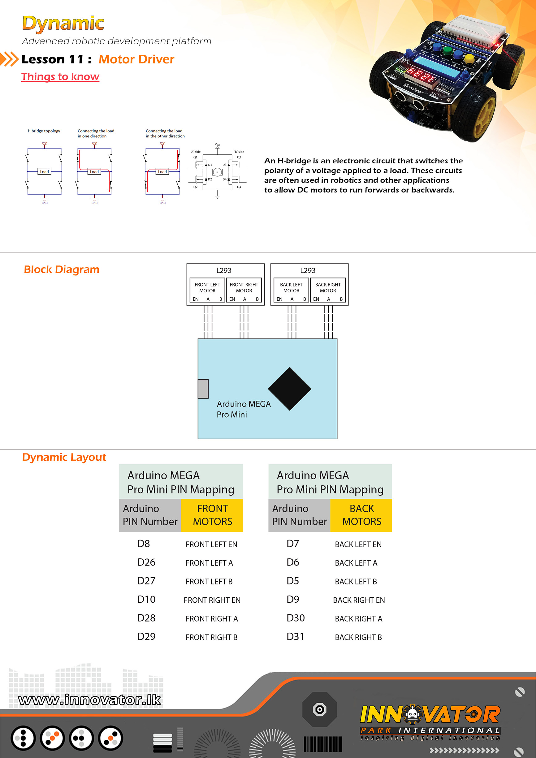
Motor Driver Example(Top Board).
---------------------------------------------------------------------------
Hardware setup for Dynamic top development board :
Motor Driver PINs are allready mapped and connected to
the Arduino MEGA board.PINs are as follows :
LEFT FRONT MOTOR EN PIN connected to Arduino digital PIN -> 8(D8)
LEFT FRONT MOTOR A PIN connected to Arduino digital PIN -> 26(D26)
LEFT FRONT MOTOR B PIN connected to Arduino digital PIN -> 27(D27)
LEFT BACK MOTOR EN PIN connected to Arduino digital PIN -> 7(D8)
LEFT BACK MOTOR A PIN connected to Arduino digital PIN -> 6(D8)
LEFT BACK MOTOR B PIN connected to Arduino digital PIN -> 5(D8)
RIGHT FRONT MOTOR EN PIN connected to Arduino digital PIN -> 10(D10)
RIGHT FRONT MOTOR A PIN connected to Arduino digital PIN -> 28(D28)
RIGHT FRONT MOTOR B PIN connected to Arduino digital PIN -> 29(D29)
RIGHT BACK MOTOR EN PIN connected to Arduino digital PIN -> 9(D9)
RIGHT BACK MOTOR A PIN connected to Arduino digital PIN -> 30(D30)
RIGHT BACK MOTOR B PIN connected to Arduino digital PIN -> 31(D31)
23 march 2021
*/
int LEFT_FRONT_MOTOR_EN = 8;// the number of the Arduino PIN, that left front motor EN PIN is connected to.
int LEFT_FRONT_MOTOR_A = 26;// the number of the Arduino PIN, that left front motor A PIN is connected to.
int LEFT_FRONT_MOTOR_B = 27;// the number of the Arduino PIN, that left front motor B PIN is connected to.
int LEFT_BACK_MOTOR_EN = 7;// the number of the Arduino PIN, that left back motor EN PIN is connected to.
int LEFT_BACK_MOTOR_B = 5;// the number of the Arduino PIN, that left back motor A PIN is connected to.
int LEFT_BACK_MOTOR_A = 6;// the number of the Arduino PIN, that left back motor B PIN is connected to.
int RIGHT_FRONT_MOTOR_EN = 10;// the number of the Arduino PIN, that right front motor EN PIN is connected to.
int RIGHT_FRONT_MOTOR_A = 28;// the number of the Arduino PIN, that right front motor A PIN is connected to.
int RIGHT_FRONT_MOTOR_B = 29;// the number of the Arduino PIN, that right front motor B PIN is connected to.
int RIGHT_BACK_MOTOR_EN = 9;// the number of the Arduino PIN, that right back motor EN PIN is connected to.
int RIGHT_BACK_MOTOR_A = 30;// the number of the Arduino PIN, that right back motor A PIN is connected to.
int RIGHT_BACK_MOTOR_B = 31;// the number of the Arduino PIN, that right back motor B PIN is connected to.
void setup() {
//making all motor driver PINs as output PINs
pinMode(LEFT_FRONT_MOTOR_EN, OUTPUT);
pinMode(LEFT_FRONT_MOTOR_A, OUTPUT);
pinMode(LEFT_FRONT_MOTOR_B, OUTPUT);
pinMode(LEFT_BACK_MOTOR_EN, OUTPUT);
pinMode(LEFT_BACK_MOTOR_A, OUTPUT);
pinMode(LEFT_BACK_MOTOR_B, OUTPUT);
pinMode(RIGHT_FRONT_MOTOR_EN, OUTPUT);
pinMode(RIGHT_FRONT_MOTOR_A, OUTPUT);
pinMode(RIGHT_FRONT_MOTOR_B, OUTPUT);
pinMode(RIGHT_BACK_MOTOR_EN, OUTPUT);
pinMode(RIGHT_BACK_MOTOR_A, OUTPUT);
pinMode(RIGHT_BACK_MOTOR_B, OUTPUT);
// turning all motors off at startup
digitalWrite(LEFT_FRONT_MOTOR_A, LOW);
digitalWrite(LEFT_FRONT_MOTOR_B, LOW);
digitalWrite(LEFT_BACK_MOTOR_A, LOW);
digitalWrite(LEFT_BACK_MOTOR_B, LOW);
digitalWrite(RIGHT_FRONT_MOTOR_A, LOW);
digitalWrite(RIGHT_FRONT_MOTOR_B, LOW);
digitalWrite(RIGHT_BACK_MOTOR_A, LOW);
digitalWrite(RIGHT_BACK_MOTOR_B, LOW);
}
void loop() {
SPEED_CONTROL();//0 to 255 pwm speed control.
delay(2000);//waiting for 2 seconds.
FOWARD();//turning all motors forward.
delay(2000);//waiting for 2 seconds.
STOP() ;//stopping all motors.
delay(2000);//waiting for 2 seconds.
BACKWARDS();//running all motors backward.
delay(2000);//waiting for 2 seconds.
LEFT();
delay(2000);//waiting for 2 seconds.
RIGHT();
delay(2000);//waiting for 2 seconds.
}
void FOWARD() {
// set motors to maximum speed.
// PWM maximum possible values are 0 to 255.
analogWrite(LEFT_FRONT_MOTOR_EN, 255);
analogWrite(LEFT_BACK_MOTOR_EN, 255);
analogWrite(RIGHT_FRONT_MOTOR_EN, 255);
analogWrite(RIGHT_BACK_MOTOR_EN, 255);
//driving all motors forward
digitalWrite(LEFT_FRONT_MOTOR_A, LOW);
digitalWrite(LEFT_FRONT_MOTOR_B, HIGH);
digitalWrite(RIGHT_FRONT_MOTOR_A, HIGH);
digitalWrite(RIGHT_FRONT_MOTOR_B, LOW);
digitalWrite(LEFT_BACK_MOTOR_A, LOW);
digitalWrite(LEFT_BACK_MOTOR_B, HIGH);
digitalWrite(RIGHT_BACK_MOTOR_A, HIGH);
digitalWrite(RIGHT_BACK_MOTOR_B, LOW);
}
void BACKWARDS() {
// set motors to maximum speed.
// PWM maximum possible values are 0 to 255.
analogWrite(LEFT_FRONT_MOTOR_EN, 255);
analogWrite(LEFT_BACK_MOTOR_EN, 255);
analogWrite(RIGHT_FRONT_MOTOR_EN, 255);
analogWrite(RIGHT_BACK_MOTOR_EN, 255);
//driving all motors backwards
digitalWrite(LEFT_FRONT_MOTOR_A, HIGH);
digitalWrite(LEFT_FRONT_MOTOR_B, LOW);
digitalWrite(RIGHT_FRONT_MOTOR_A, LOW);
digitalWrite(RIGHT_FRONT_MOTOR_B, HIGH);
digitalWrite(LEFT_BACK_MOTOR_A, HIGH);
digitalWrite(LEFT_BACK_MOTOR_B, LOW);
digitalWrite(RIGHT_BACK_MOTOR_A, LOW);
digitalWrite(RIGHT_BACK_MOTOR_B, HIGH);
}
void STOP() {
// turn off all motors.
digitalWrite(LEFT_FRONT_MOTOR_A, LOW);
digitalWrite(LEFT_FRONT_MOTOR_B, LOW);
digitalWrite(RIGHT_FRONT_MOTOR_A, LOW);
digitalWrite(RIGHT_FRONT_MOTOR_B, LOW);
digitalWrite(LEFT_BACK_MOTOR_A, LOW);
digitalWrite(LEFT_BACK_MOTOR_B, LOW);
digitalWrite(RIGHT_BACK_MOTOR_A, LOW);
digitalWrite(RIGHT_BACK_MOTOR_B, LOW);
}
void LEFT() {
analogWrite(LEFT_FRONT_MOTOR_EN, 255);
analogWrite(LEFT_BACK_MOTOR_EN, 255);
analogWrite(RIGHT_FRONT_MOTOR_EN, 255);
analogWrite(RIGHT_BACK_MOTOR_EN, 255);
digitalWrite(LEFT_FRONT_MOTOR_A, HIGH);
digitalWrite(LEFT_FRONT_MOTOR_B, LOW);
digitalWrite(RIGHT_FRONT_MOTOR_A, HIGH);
digitalWrite(RIGHT_FRONT_MOTOR_B, LOW);
digitalWrite(LEFT_BACK_MOTOR_A, HIGH);
digitalWrite(LEFT_BACK_MOTOR_B, LOW);
digitalWrite(RIGHT_BACK_MOTOR_A, HIGH);
digitalWrite(RIGHT_BACK_MOTOR_B, LOW);
}
void RIGHT() {
analogWrite(LEFT_FRONT_MOTOR_EN, 255);
analogWrite(LEFT_BACK_MOTOR_EN, 255);
analogWrite(RIGHT_FRONT_MOTOR_EN, 255);
analogWrite(RIGHT_BACK_MOTOR_EN, 255);
digitalWrite(LEFT_FRONT_MOTOR_A, LOW);
digitalWrite(LEFT_FRONT_MOTOR_B, HIGH);
digitalWrite(RIGHT_FRONT_MOTOR_A, LOW);
digitalWrite(RIGHT_FRONT_MOTOR_B, HIGH);
digitalWrite(LEFT_BACK_MOTOR_A, LOW);
digitalWrite(LEFT_BACK_MOTOR_B, HIGH);
digitalWrite(RIGHT_BACK_MOTOR_A, LOW);
digitalWrite(RIGHT_BACK_MOTOR_B, HIGH);
}
void SPEED_CONTROL() {
digitalWrite(LEFT_FRONT_MOTOR_A, LOW);
digitalWrite(LEFT_FRONT_MOTOR_B, HIGH);
digitalWrite(RIGHT_FRONT_MOTOR_A, LOW);
digitalWrite(RIGHT_FRONT_MOTOR_B, HIGH);
digitalWrite(LEFT_BACK_MOTOR_A, LOW);
digitalWrite(LEFT_BACK_MOTOR_B, HIGH);
digitalWrite(RIGHT_BACK_MOTOR_A, LOW);
digitalWrite(RIGHT_BACK_MOTOR_B, HIGH);
// accelerate from zero to maximum speed
for (int i = 0; i < 256; i++) { analogWrite(LEFT_FRONT_MOTOR_EN, i); analogWrite(RIGHT_FRONT_MOTOR_EN, i); analogWrite(LEFT_BACK_MOTOR_EN, i); analogWrite(RIGHT_BACK_MOTOR_EN, i); delay(20); } // decelerate from maximum speed to zero for (int i = 255; i >= 0; --i) {
analogWrite(LEFT_FRONT_MOTOR_EN, i);
analogWrite(RIGHT_FRONT_MOTOR_EN, i);
analogWrite(LEFT_BACK_MOTOR_EN, i);
analogWrite(RIGHT_BACK_MOTOR_EN, i);
delay(20);
}
// turning all motors off
digitalWrite(LEFT_FRONT_MOTOR_A, LOW);
digitalWrite(LEFT_FRONT_MOTOR_B, LOW);
digitalWrite(RIGHT_FRONT_MOTOR_A, LOW);
digitalWrite(RIGHT_FRONT_MOTOR_B, LOW);
digitalWrite(LEFT_BACK_MOTOR_A, LOW);
digitalWrite(LEFT_BACK_MOTOR_B, LOW);
digitalWrite(RIGHT_BACK_MOTOR_A, LOW);
digitalWrite(RIGHT_BACK_MOTOR_B, LOW);
} 
/*
INNOVATOR INTERNATIONAL (PVT)LTD.
https://www.innovator.lk/
--------------------------------------------------------------------------
Development Platform : Dynamic 1.0
(mobile robot development platform)
---------------------------------------------------------------------------
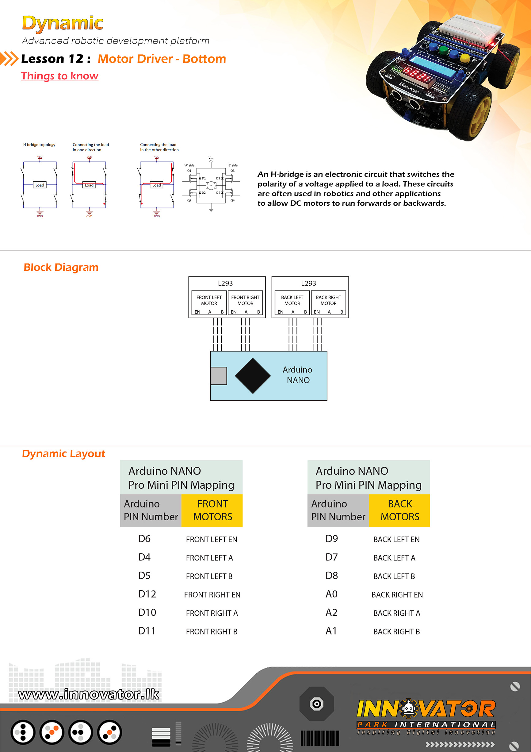
Motor Driver Example(Bottom Board).
---------------------------------------------------------------------------
Hardware setup for Dynamic bottom development board :
Motor Driver PINs are allready mapped and connected to
the Arduino NANO board.PINs are as follows :
LEFT FRONT MOTOR EN PIN connected to Arduino digital PIN -> 6(D6)
LEFT FRONT MOTOR A PIN connected to Arduino digital PIN -> 4(D4)
LEFT FRONT MOTOR B PIN connected to Arduino digital PIN -> 5(D5)
LEFT BACK MOTOR EN PIN connected to Arduino digital PIN -> 9(D9)
LEFT BACK MOTOR A PIN connected to Arduino digital PIN -> 7(D7)
LEFT BACK MOTOR B PIN connected to Arduino digital PIN -> 8(D8)
RIGHT FRONT MOTOR EN PIN connected to Arduino digital PIN -> 12(D12)
RIGHT FRONT MOTOR A PIN connected to Arduino digital PIN -> 10(D10)
RIGHT FRONT MOTOR B PIN connected to Arduino digital PIN -> 11(D11)
RIGHT BACK MOTOR EN PIN connected to Arduino analog PIN -> A0(A0)
RIGHT BACK MOTOR A PIN connected to Arduino analog PIN -> A2(A2)
RIGHT BACK MOTOR B PIN connected to Arduino analog PIN -> A1(A1)
---------------------------------------------------------------------------
23 march 2021
*/
int LEFT_FRONT_MOTOR_EN = 6;// the number of the Arduino PIN, that left front motor EN PIN is connected to.
int LEFT_FRONT_MOTOR_A = 4;// the number of the Arduino PIN, that left front motor A PIN is connected to.
int LEFT_FRONT_MOTOR_B = 5;// the number of the Arduino PIN, that left front motor B PIN is connected to.
int LEFT_BACK_MOTOR_EN = 9;// the number of the Arduino PIN, that left back motor EN PIN is connected to.
int LEFT_BACK_MOTOR_B = 8;// the number of the Arduino PIN, that left back motor A PIN is connected to.
int LEFT_BACK_MOTOR_A = 7;// the number of the Arduino PIN, that left back motor B PIN is connected to.
int RIGHT_FRONT_MOTOR_EN = 12;// the number of the Arduino PIN, that right front motor EN PIN is connected to.
int RIGHT_FRONT_MOTOR_A = 10;// the number of the Arduino PIN, that right front motor A PIN is connected to.
int RIGHT_FRONT_MOTOR_B = 11;// the number of the Arduino PIN, that right front motor B PIN is connected to.
int RIGHT_BACK_MOTOR_EN = A0;// the number of the Arduino PIN, that right back motor EN PIN is connected to.
int RIGHT_BACK_MOTOR_A = A2;// the number of the Arduino PIN, that right back motor A PIN is connected to.
int RIGHT_BACK_MOTOR_B = A1;// the number of the Arduino PIN, that right back motor B PIN is connected to.
void setup() {
//making all motor driver PINs as output PINs
pinMode(LEFT_FRONT_MOTOR_EN, OUTPUT);
pinMode(LEFT_FRONT_MOTOR_A, OUTPUT);
pinMode(LEFT_FRONT_MOTOR_B, OUTPUT);
pinMode(LEFT_BACK_MOTOR_EN, OUTPUT);
pinMode(LEFT_BACK_MOTOR_A, OUTPUT);
pinMode(LEFT_BACK_MOTOR_B, OUTPUT);
pinMode(RIGHT_FRONT_MOTOR_EN, OUTPUT);
pinMode(RIGHT_FRONT_MOTOR_A, OUTPUT);
pinMode(RIGHT_FRONT_MOTOR_B, OUTPUT);
pinMode(RIGHT_BACK_MOTOR_EN, OUTPUT);
pinMode(RIGHT_BACK_MOTOR_A, OUTPUT);
pinMode(RIGHT_BACK_MOTOR_B, OUTPUT);
// turning all motors off at startup
digitalWrite(LEFT_FRONT_MOTOR_A, LOW);
digitalWrite(LEFT_FRONT_MOTOR_B, LOW);
digitalWrite(LEFT_BACK_MOTOR_A, LOW);
digitalWrite(LEFT_BACK_MOTOR_B, LOW);
digitalWrite(RIGHT_FRONT_MOTOR_A, LOW);
digitalWrite(RIGHT_FRONT_MOTOR_B, LOW);
digitalWrite(RIGHT_BACK_MOTOR_A, LOW);
digitalWrite(RIGHT_BACK_MOTOR_B, LOW);
}
void loop() {
SPEED_CONTROL();
delay(2000);
FOWARD();
delay(2000);
STOP() ;
delay(2000);
BACKWARDS();
delay(2000);
}
void FOWARD() {
// set motors to maximum speed.
// PWM maximum possible values are 0 to 255.
analogWrite(LEFT_FRONT_MOTOR_EN, 255);
analogWrite(LEFT_BACK_MOTOR_EN, 255);
analogWrite(RIGHT_FRONT_MOTOR_EN, 255);
analogWrite(RIGHT_BACK_MOTOR_EN, 255);
//driving all motors forward
digitalWrite(LEFT_FRONT_MOTOR_A, LOW);
digitalWrite(LEFT_FRONT_MOTOR_B, HIGH);
digitalWrite(RIGHT_FRONT_MOTOR_A, HIGH);
digitalWrite(RIGHT_FRONT_MOTOR_B, LOW);
digitalWrite(LEFT_BACK_MOTOR_A, LOW);
digitalWrite(LEFT_BACK_MOTOR_B, HIGH);
digitalWrite(RIGHT_BACK_MOTOR_A, HIGH);
digitalWrite(RIGHT_BACK_MOTOR_B, LOW);
}
void BACKWARDS() {
// set motors to maximum speed.
// PWM maximum possible values are 0 to 255.
analogWrite(LEFT_FRONT_MOTOR_EN, 255);
analogWrite(LEFT_BACK_MOTOR_EN, 255);
analogWrite(RIGHT_FRONT_MOTOR_EN, 255);
analogWrite(RIGHT_BACK_MOTOR_EN, 255);
//driving all motors backwards
digitalWrite(LEFT_FRONT_MOTOR_A, HIGH);
digitalWrite(LEFT_FRONT_MOTOR_B, LOW);
digitalWrite(RIGHT_FRONT_MOTOR_A, LOW);
digitalWrite(RIGHT_FRONT_MOTOR_B, HIGH);
digitalWrite(LEFT_BACK_MOTOR_A, HIGH);
digitalWrite(LEFT_BACK_MOTOR_B, LOW);
digitalWrite(RIGHT_BACK_MOTOR_A, LOW);
digitalWrite(RIGHT_BACK_MOTOR_B, HIGH);
}
void STOP() {
// turn off all motors.
digitalWrite(LEFT_FRONT_MOTOR_A, LOW);
digitalWrite(LEFT_FRONT_MOTOR_B, LOW);
digitalWrite(RIGHT_FRONT_MOTOR_A, LOW);
digitalWrite(RIGHT_FRONT_MOTOR_B, LOW);
digitalWrite(LEFT_BACK_MOTOR_A, LOW);
digitalWrite(LEFT_BACK_MOTOR_B, LOW);
digitalWrite(RIGHT_BACK_MOTOR_A, LOW);
digitalWrite(RIGHT_BACK_MOTOR_B, LOW);
}
void SPEED_CONTROL() {
// Turn on motors
digitalWrite(LEFT_FRONT_MOTOR_A, LOW);
digitalWrite(LEFT_FRONT_MOTOR_B, HIGH);
digitalWrite(RIGHT_FRONT_MOTOR_A, HIGH);
digitalWrite(RIGHT_FRONT_MOTOR_B, LOW);
digitalWrite(LEFT_BACK_MOTOR_A, LOW);
digitalWrite(LEFT_BACK_MOTOR_B, HIGH);
digitalWrite(RIGHT_BACK_MOTOR_A, HIGH);
digitalWrite(RIGHT_BACK_MOTOR_B, LOW);
// accelerate from zero to maximum speed
for (int i = 0; i < 256; i++) { analogWrite(LEFT_FRONT_MOTOR_EN, i); analogWrite(RIGHT_FRONT_MOTOR_EN, i); analogWrite(LEFT_BACK_MOTOR_EN, i); analogWrite(RIGHT_BACK_MOTOR_EN, i); delay(20); } // decelerate from maximum speed to zero for (int i = 255; i >= 0; --i) {
analogWrite(LEFT_FRONT_MOTOR_EN, i);
analogWrite(RIGHT_FRONT_MOTOR_EN, i);
analogWrite(LEFT_BACK_MOTOR_EN, i);
analogWrite(RIGHT_BACK_MOTOR_EN, i);
delay(20);
}
// turning all motors off
digitalWrite(LEFT_FRONT_MOTOR_A, LOW);
digitalWrite(LEFT_FRONT_MOTOR_B, LOW);
digitalWrite(RIGHT_FRONT_MOTOR_A, LOW);
digitalWrite(RIGHT_FRONT_MOTOR_B, LOW);
digitalWrite(LEFT_BACK_MOTOR_A, LOW);
digitalWrite(LEFT_BACK_MOTOR_B, LOW);
digitalWrite(RIGHT_BACK_MOTOR_A, LOW);
digitalWrite(RIGHT_BACK_MOTOR_B, LOW);
}
/*
INNOVATOR INTERNATIONAL (PVT)LTD.
https://www.innovator.lk/
-----------------------------------------------------------
Development Platform : Dynamic 1.0
(mobile robot development platform)
-----------------------------------------------------------
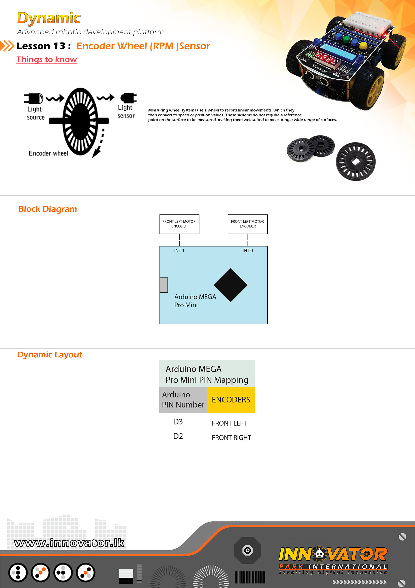
RPM Example.
-----------------------------------------------------------
Hardware setup :
Optical Encoder PINs are already mapped and connected to
the Arduino board.PINs are as follows :
LEFT ENCODER connected to Arduino digital PIN -> 2(D2)
RIGHT ENCODER connected to Arduino digital PIN -> 3(D3)
-----------------------------------------------------------
24 march 2021
*/
int LEFT_ENCODER_COUNTER = 0, RIGHT_ENCODER_COUNTER = 0; //variable to hold the encoder counts.
unsigned long TIME_NOW = 0, TIME_ELAPSED = 0;//variables to hold the delay timer values.
float LEFT_WHEEL, RIGHT_WHEEL; //variables to hold the rpm values.
int LEFT_FRONT_MOTOR_EN = 8;// the number of the Arduino PIN, that left front motor EN PIN is connected to.
int LEFT_FRONT_MOTOR_A = 26;// the number of the Arduino PIN, that left front motor A PIN is connected to.
int LEFT_FRONT_MOTOR_B = 27;// the number of the Arduino PIN, that left front motor B PIN is connected to.
int RIGHT_FRONT_MOTOR_EN = 10;// the number of the Arduino PIN, that right front motor EN PIN is connected to.
int RIGHT_FRONT_MOTOR_A = 28;// the number of the Arduino PIN, that right front motor A PIN is connected to.
int RIGHT_FRONT_MOTOR_B = 29;// the number of the Arduino PIN, that right front motor B PIN is connected to.
void setup() {
Serial.begin(9600);//starting serial communication between arduino and computer.
attachInterrupt(0, Right_Encoder_Count, RISING);//enabling Arduino digital PIN 2(D2)falling edge interrupt.
attachInterrupt(1, Left_Encoder_Count, RISING);//enabling Arduino digital PIN 3(D3)falling edge interrupt.
delay(1000);
pinMode(LEFT_FRONT_MOTOR_EN, OUTPUT);
pinMode(LEFT_FRONT_MOTOR_A, OUTPUT);
pinMode(LEFT_FRONT_MOTOR_B, OUTPUT);
pinMode(RIGHT_FRONT_MOTOR_EN, OUTPUT);
pinMode(RIGHT_FRONT_MOTOR_A, OUTPUT);
pinMode(RIGHT_FRONT_MOTOR_B, OUTPUT);
}
void loop() {
analogWrite(RIGHT_FRONT_MOTOR_EN, 255);
digitalWrite(RIGHT_FRONT_MOTOR_A, HIGH);
digitalWrite(RIGHT_FRONT_MOTOR_B, LOW);
analogWrite(LEFT_FRONT_MOTOR_EN, 255);
digitalWrite(LEFT_FRONT_MOTOR_A, LOW);
digitalWrite(LEFT_FRONT_MOTOR_B, HIGH);
TIME_NOW = millis();//storing the currunt millis count in the variable.
if (abs(TIME_NOW - TIME_ELAPSED) >= 1000) {//check if delay time has elapsed.
detachInterrupt(0);//disabaling Arduino digital PIN 1(D1) falling edge interrupt.
detachInterrupt(1);//disabaling Arduino digital PIN 1(D1) falling edge interrupt.
//doing the RPM calculation and storing the values in variables.
LEFT_WHEEL = (float)LEFT_ENCODER_COUNTER * 60 / 20;
RIGHT_WHEEL = (float)RIGHT_ENCODER_COUNTER * 60 / 20;
//printing values to serial monitor.
Serial.print("left:");
Serial.print(LEFT_WHEEL);
Serial.print(" right:");
Serial.println(RIGHT_WHEEL);
//resetting variable values.
LEFT_ENCODER_COUNTER = 0;
RIGHT_ENCODER_COUNTER = 0;
TIME_ELAPSED = millis();
//enabaling inturrupts again.
attachInterrupt(0, Right_Encoder_Count, FALLING);
attachInterrupt(1, Left_Encoder_Count, FALLING);
return 1;//if delay time has elapsed then value is 1.
} else {
return 0;//if delay time has not elapsed then value is 0.
}
}
//incrementing the encoder counters.
//these functions are called by inturrupt routein.
void Right_Encoder_Count()
{
RIGHT_ENCODER_COUNTER++;
}
void Left_Encoder_Count()
{
LEFT_ENCODER_COUNTER++;
}
/*
INNOVATOR INTERNATIONAL (PVT)LTD.
https://www.innovator.lk/
-----------------------------------------------------------------
Development Platform : Dynamic 1.0
(mobile robot development platform)
-----------------------------------------------------------------
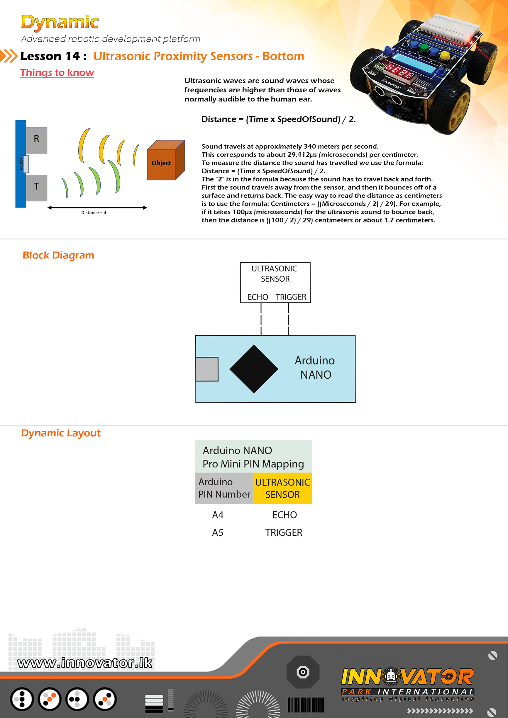
hc-sr04 Ultrasonic Distance Sensor Example.
-----------------------------------------------------------------
Hardware setup :
PINS of the ultrasonic sensors are already mapped and
connected.PINs are as follows :
front ultrasonic sensor TRIG PIN -> Arduino analog PIN 5(A5)
front ultrasonic sensor ECHO PIN -> Arduino analog PIN 4(A4)
-----------------------------------------------------------------
23 march 2021
*/
const int TRIG_PIN = A5; // the number of the PIN, that front ultrasonic sensor's trigger PIN is connected to.
const int ECHO_PIN = A4;// the number of the PIN, that front ultrasonic sensor's echo PIN is connected to.
long DURATION;//variable to store the duration.
int DISTANCE;//variable to store the duration.
void setup() {
//initializing all TRIG PINs as outputs.
pinMode(TRIG_PIN, OUTPUT);
//initializing all ECHO PINs as outputs.
pinMode(ECHO_PIN, INPUT);
Serial.begin(9600);//starting serial communication between arduino and computer.
}
void loop() {
digitalWrite(TRIG_PIN, LOW);//turning off the trigger if its already on.
delayMicroseconds(2);//waiting for two microseconds.
//doing the calculations
DURATION = pulseIn(ECHO_PIN, HIGH);
DISTANCE = DURATION * 0.034 / 2;
//printing calculations to the serial monitor.
Serial.print("DISTANCE: ");
Serial.print(DISTANCE);
}
/*
INNOVATOR INTERNATIONAL (PVT)LTD.
https://www.innovator.lk/
-------------------------------------------------------------------
Development Platform : Dynamic 1.0
(mobile robot development platform)
-------------------------------------------------------------------
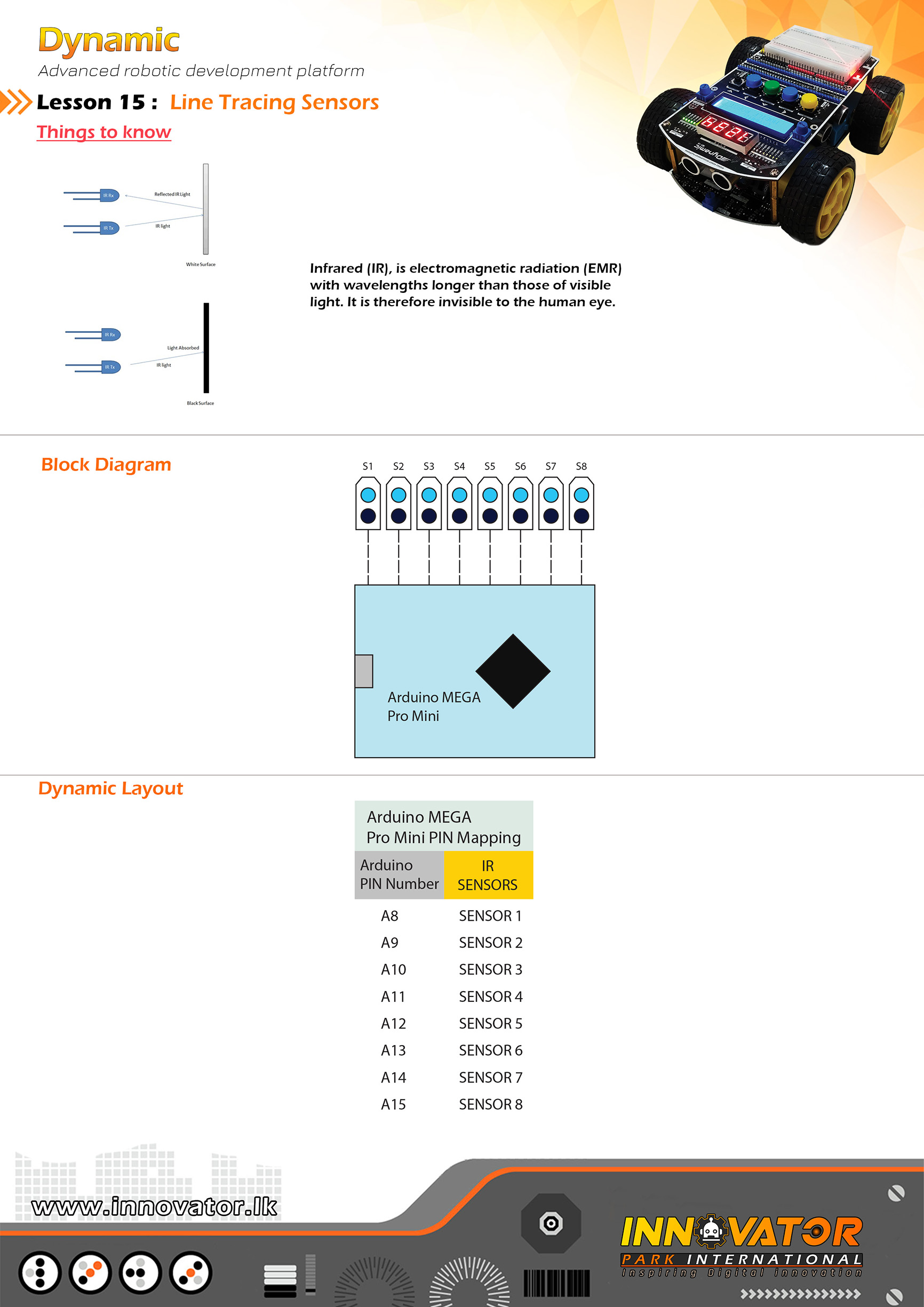
TCRT5000 Line Following Sensors Example.
-------------------------------------------------------------------
Hardware setup :
The line tracing sensors and the LEDs are allready
mapped and connected to the Arduino board.
PINs are as follows :
LINE TRACING SENSOR 1: connected to Arduino analog PIN -> 8(A8)
LINE TRACING SENSOR 2: connected to Arduino analog PIN -> 9(A9)
LINE TRACING SENSOR 3: connected to Arduino analog PIN -> 10(A10)
LINE TRACING SENSOR 4: connected to Arduino analog PIN -> 11(A11)
LINE TRACING SENSOR 5: connected to Arduino analog PIN -> 12(A12)
LINE TRACING SENSOR 6: connected to Arduino analog PIN -> 13(A13)
LINE TRACING SENSOR 7: connected to Arduino analog PIN -> 14(A14)
LINE TRACING SENSOR 8: connected to Arduino analog PIN -> 15(A15)
-------------------------------------------------------------------
PINs of the LEDs(these LEDs are already connected and mapped)
that are used to indicate the line tracing sensors are follows :
LED 1 PIN connected to Arduino digital PIN -> 22(D22)
LED 1 PIN connected to Arduino digital PIN -> 23(D23)
LED 1 PIN connected to Arduino digital PIN -> 24(D24)
LED 1 PIN connected to Arduino digital PIN -> 25(D25)
LED 1 PIN connected to Arduino digital PIN -> 32(D32)
LED 1 PIN connected to Arduino digital PIN -> 33(D33)
LED 1 PIN connected to Arduino digital PIN -> 34(D34)
LED 1 PIN connected to Arduino digital PIN -> 35(D35)
-------------------------------------------------------------------
23 march 2021
*/
int IR1 = A8; // the number of the Arduino PIN, that line tracing sensor 1 is connected to.
int IR2 = A9; // the number of the Arduino PIN, that line tracing sensor 2 is connected to.
int IR3 = A10;// the number of the Arduino PIN, that line tracing sensor 3 is connected to.
int IR4 = A11;// the number of the Arduino PIN, that line tracing sensor 4 is connected to.
int IR5 = A12;// the number of the Arduino PIN, that line tracing sensor 5 is connected to.
int IR6 = A13;// the number of the Arduino PIN, that line tracing sensor 6 is connected to.
int IR7 = A14;// the number of the Arduino PIN, that line tracing sensor 7 is connected to.
int IR8 = A15;// the number of the Arduino PIN, that line tracing sensor 8 is connected to.
int LED1 = 22;// the number of the Arduino PIN, that LED 1 is connected to.
int LED2 = 23;// the number of the Arduino PIN, that LED 2 is connected to.
int LED3 = 24;// the number of the Arduino PIN, that LED 3 is connected to.
int LED4 = 25;// the number of the Arduino PIN, that LED 4 is connected to.
int LED5 = 32;// the number of the Arduino PIN, that LED 5 is connected to.
int LED6 = 33;// the number of the Arduino PIN, that LED 6 is connected to.
int LED7 = 34;// the number of the Arduino PIN, that LED 7 is connected to.
int LED8 = 35;// the number of the Arduino PIN, that LED 8 is connected to.
int s1, s2, s3, s4, s5 , s6, s7, s8; // creating few variables to hold the each line tracing sensor value.
void setup() {
//making all PINs connected as line tracing sensors to be input's.
pinMode(IR1, INPUT);
pinMode(IR2, INPUT);
pinMode(IR3, INPUT);
pinMode(IR4, INPUT);
pinMode(IR5, INPUT);
pinMode(IR6, INPUT);
pinMode(IR7, INPUT);
pinMode(IR8, INPUT);
//making all LED PINs as outputs.
pinMode(LED1, OUTPUT);
pinMode(LED2, OUTPUT);
pinMode(LED3, OUTPUT);
pinMode(LED4, OUTPUT);
pinMode(LED5, OUTPUT);
pinMode(LED6, OUTPUT);
pinMode(LED7, OUTPUT);
pinMode(LED8, OUTPUT);
}
void loop() {
//reading each line tracing sensors to variables.
s1 = digitalRead(IR1);
s2 = digitalRead(IR2);
s3 = digitalRead(IR3);
s4 = digitalRead(IR4);
s5 = digitalRead(IR5);
s6 = digitalRead(IR6);
s7 = digitalRead(IR7);
s8 = digitalRead(IR8);
//check the variable values and turning on off corrosponding LED's.
if (s1) {
digitalWrite(LED1, LOW);
} else {
digitalWrite(LED1, HIGH);
}
if (s2) {
digitalWrite(LED2, LOW);
} else {
digitalWrite(LED2, HIGH);
}
if (s3) {
digitalWrite(LED3, LOW);
} else {
digitalWrite(LED3, HIGH);
}
if (s4) {
digitalWrite(LED4, LOW);
} else {
digitalWrite(LED4, HIGH);
}
if (s5) {
digitalWrite(LED5, LOW);
} else {
digitalWrite(LED5, HIGH);
}
if (s6) {
digitalWrite(LED6, LOW);
} else {
digitalWrite(LED6, HIGH);
}
if (s7) {
digitalWrite(LED7, LOW);
} else {
digitalWrite(LED7, HIGH);
}
if (s8) {
digitalWrite(LED8, LOW);
} else {
digitalWrite(LED8, HIGH);
}
}
/*
INNOVATOR INTERNATIONAL (PVT)LTD.
https://www.innovator.lk/
----------------------------------------------------------------------------
Development Platform : Dynamic 1.0
(mobile robot development platform)
----------------------------------------------------------------------------
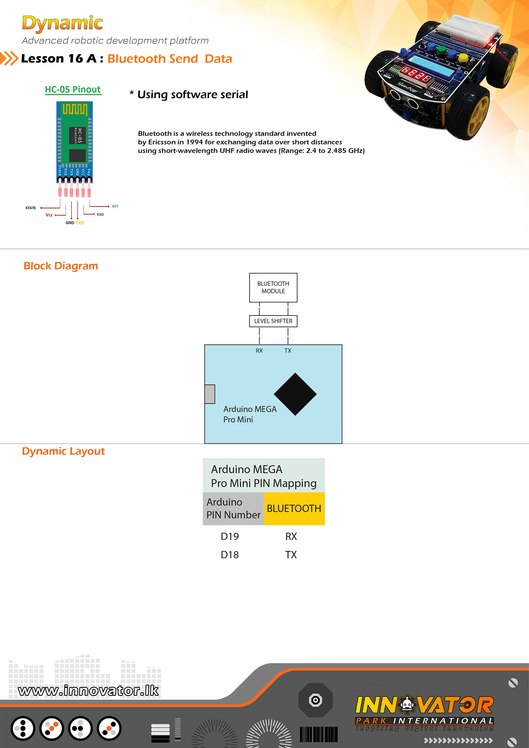
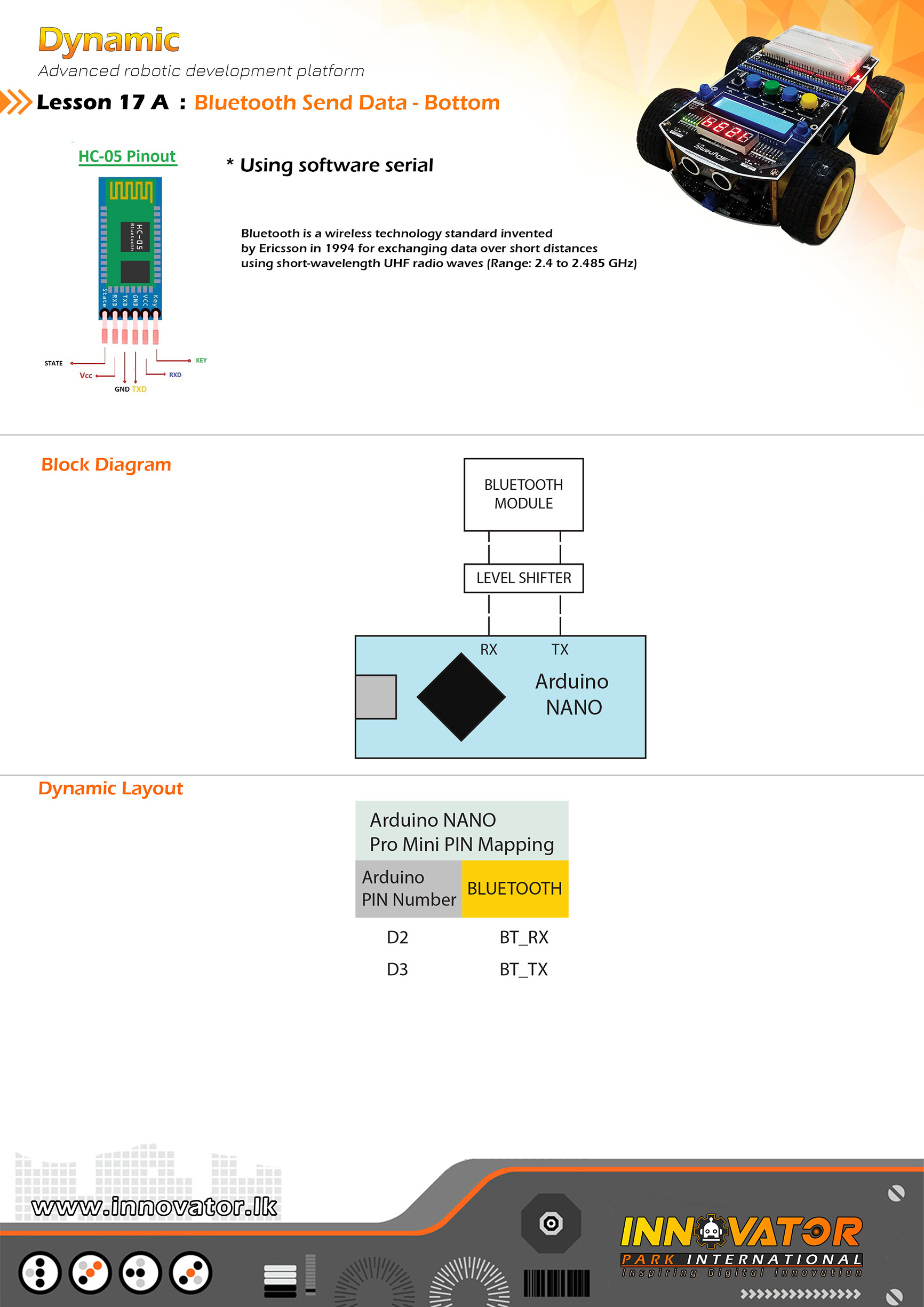
Bluetooth Send Example.
----------------------------------------------------------------------------
Hardware setup :
built-in bluetooth module already mapped and connected to
Arduino board. the PINs are as follows:
BT_TX connected to Arduino digital PIN18(D18)
BT_RX connected to Arduino digital PIN19(D19)
Serial 1 on Atmega PRO MINI
----------------------------------------------------------------------------
//Android application used for this example:
//https://play.google.com/store/apps/details?id=project.bluetoothterminal
----------------------------------------------------------------------------
23 march 2021
*/
void setup() {
Serial1.begin(9600);//starting software serial communication.
}
void loop() {
Serial1.println("this is from Dynamic :) ");//printing a message to software serial.
delay(1000);//keep a one second delay between each serial print.
}
/*
INNOVATOR INTERNATIONAL (PVT)LTD.
https://www.innovator.lk/
----------------------------------------------------------------------------
Development Platform : Dynamic 1.0
(mobile robot development platform)
----------------------------------------------------------------------------
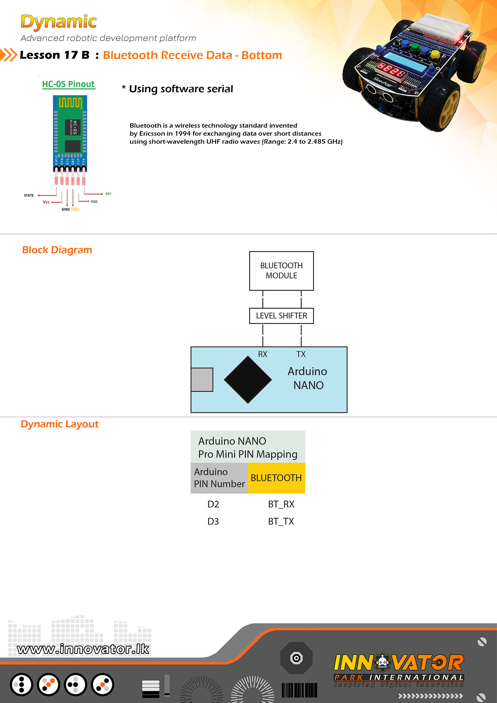
Bluetooth Receive Example.
----------------------------------------------------------------------------
Hardware setup :
built-in bluetooth module already mapped and connected to
Arduino board. the PINs are as follows:
BT_TX connected to Arduino digital PIN18(D18)
BT_RX connected to Arduino digital PIN19(D19)
Serial 1 on Atmega PRO MINI
-----------------------------------------------------------------------------
//Android application used for this example:
//https://play.google.com/store/apps/details?id=project.bluetoothterminal
-----------------------------------------------------------------------------
23 march 2021
*/
char c;//variable to hold the character recived by the serial data.
void setup() {
Serial1.begin(9600);//starting software serial communication.
Serial.begin(9600);//starting serial communication between arduino and computer.
}
void loop() {
if (Serial1.available() > 0) {//check if software serial is containing any data.
while (Serial1.available() > 0) {//while there is data,
c = Serial1.read();//read it and store it in the variable called "c".
Serial.print(c);//printing stored variable to the serial monitor.
}
}
}
/*
  INNOVATOR INTERNATIONAL (PVT)LTD.
  https://www.innovator.lk/
  ----------------------------------------------------------------------------
  Development Platform : Dynamic 1.0
  (mobile robot development platform)
  ----------------------------------------------------------------------------
  Bluetooth Send Example.
  ----------------------------------------------------------------------------
  Hardware setup :
  built-in bluetooth module already mapped and connected to
  Arduino board. the PINs are as follows:

  BT_TX connected to Arduino digital PIN 2(D2)
  BT_RX connected to Arduino digital PIN 3(D3)
  Serial 1 on Atmega PRO MINI
  ----------------------------------------------------------------------------
  //Android application used for this example:
  //https://play.google.com/store/apps/details?id=project.bluetoothterminal
  ----------------------------------------------------------------------------
  23 march 2021
*/

void setup() {
  Serial1.begin(9600);//starting software serial communication.
}

void loop() {
  Serial1.println("this is from Dynamic :) ");//printing a message to software serial.

  delay(1000);//keep a one second delay between each serial print.
}
/*
  INNOVATOR INTERNATIONAL (PVT)LTD.
  https://www.innovator.lk/
  ----------------------------------------------------------------------------
  Development Platform : Dynamic 1.0
  (mobile robot development platform)
  ----------------------------------------------------------------------------
  Bluetooth Receive Example.
  ----------------------------------------------------------------------------
  Hardware setup :
  built-in bluetooth module already mapped and connected to
  Arduino board. the PINs are as follows:

  BT_TX connected to Arduino digital PIN 2(D2)
  BT_RX connected to Arduino digital PIN 3(D3)
  Serial 1 on Atmega PRO MINI
  -----------------------------------------------------------------------------
  //Android application used for this example:
  //https://play.google.com/store/apps/details?id=project.bluetoothterminal
  -----------------------------------------------------------------------------
  23 march 2021
*/

char c;//variable to hold the character recived by the serial data.

void setup() {
  Serial1.begin(9600);//starting software serial communication.

  Serial.begin(9600);//starting serial communication between arduino and computer.
}

void loop() {
  if (Serial1.available() > 0) {//check if software serial is containing any data.

    while (Serial1.available() > 0) {//while there is data,

      c = Serial1.read();//read it and store it in the variable called "c".

      Serial.print(c);//printing stored variable to the serial monitor.
    }
  }
}
/*
  INNOVATOR INTERNATIONAL (PVT)LTD.
  https://www.innovator.lk/
  ---------------------------------------------------------------------------
  Development Platform : Dynamic 1.0
  (mobile robot development platform)
  ---------------------------------------------------------------------------
  ESP1 (esp8266) wifi example.
  controling a led through wifi
  ---------------------------------------------------------------------------
  Hardware setup :
  //connect RX of wifi to MCU RX0.
  //connect TX of wifi to MCU TX0.
  //connect MCU RST pin to one of the GND pins.

  //pres and hold GPIO0 and RST buttons together and release the RST button first then GPIO0.
  //this will put the esp8266 to programing mode.
  //now press upload button in arduin IDE.
  ---------------------------------------------------------------------------
  23 march 2021
*/

#include "ESP8266WiFi.h"
const char* ssid = "**********";//type your ssid
const char* password = "**********";//type your password

int ledPin = 2; // GPIO2 of ESP8266
WiFiServer server(80);

void setup() {
  Serial.begin(115200);
  delay(10);


  pinMode(ledPin, OUTPUT);
  digitalWrite(ledPin, LOW);

  // Connect to WiFi network
  Serial.println();
  Serial.println();
  Serial.print("Connecting to ");
  Serial.println(ssid);

  WiFi.begin(ssid, password);

  while (WiFi.status() != WL_CONNECTED) {
    delay(500);
    Serial.print(".");
  }
  Serial.println("");
  Serial.println("WiFi connected");

  // Start the server
  server.begin();
  Serial.println("Server started");

  // Print the IP address
  Serial.print("Use this URL to connect: ");
  Serial.print("http://");
  Serial.print(WiFi.localIP());
  Serial.println("/");

}

void loop() {
  // Check if a client has connected
  WiFiClient client = server.available();
  if (!client) {
    return;
  }

  // Wait until the client sends some data
  Serial.println("new client");
  while (!client.available()) {
    delay(1);
  }

  // Read the first line of the request
  String request = client.readStringUntil('r');
  Serial.println(request);
  client.flush();

  // Match the request

  int value = LOW;
  if (request.indexOf("/LED=ON") != -1) {
    digitalWrite(ledPin, LOW);
    value = HIGH;
  }
  if (request.indexOf("/LED=OFF") != -1) {
    digitalWrite(ledPin, HIGH);
    value = LOW;
  }

  // Set ledPin according to the request
  //digitalWrite(ledPin, value);


  // Return the response
  client.println("HTTP/1.1 200 OK");
  client.println("Content-Type: text/html");
  client.println(""); //  do not forget this one
  client.println("");
  client.println("");

  client.print("Led pin is now: ");

  if (value == HIGH) {
    client.print("On");
  } else {
    client.print("Off");
  }
  client.println("");
  client.println("Click here turn the LED on pin 2 ON");
  client.println("Click here turn the LED on pin 2 OFF");
  client.println("");

  delay(1);
  Serial.println("Client disonnected");
  Serial.println("");

}/*
INNOVATOR INTERNATIONAL (PVT)LTD.
https://www.innovator.lk/
--------------------------------------------------------
Development Platform : Dynamic 1.0
(mobile robot development platform)
--------------------------------------------------------
SSD DICE.
--------------------------------------------------------
Hardware setup :
Seven Segment Display Driver(7219) PINs are allready
mapped and connected to the Arduino board.
PINs are as follows :
--------------------------------------------------------
Hardware setup :
DIN connected to Arduino digital PIN -> 51
CS connected to Arduino digital PIN -> 52
CLK connected to Arduino digital PIN -> 53
16*2 LCD is allready connected to the Arduino board.
LCD's I2C adress is 0x27.
--------------------------------------------------------
5 may 2021
*/
#include "LedControl.h"
#include "LiquidCrystal_I2C.h"
int DIN = 51;
int CLK = 52;
int CS = 53;
LedControl lc = LedControl(DIN, CLK, CS, 1);
LiquidCrystal_I2C lcd(0x27, 16, 2);
int START_BUTTON = A1;
int STOP_BUTTON = A2;
boolean RUN = false;
int RANDOM_NUMBER = 0;
void setup() {
lcd.begin();
lcd.backlight();
lcd.setCursor(0, 0);
lcd.print(" SSD Dice");
delay(1000);
lc.shutdown(0, false);
lc.setIntensity(0, 15);
lc.clearDisplay(0);
lc.setDigit(0, 3, 1, false);
lc.setDigit(0, 2, 2, true);
lc.setDigit(0, 1, 3, true);
lc.setDigit(0, 0, 4, false);
}
void loop() {
if (!digitalRead(START_BUTTON)) {
RUN = true;
delay(100);
}
if (!digitalRead(STOP_BUTTON)) {
RUN = false;
RANDOM_NUMBER = random(1, 7);
lc.setDigit(0, 3, 0, true);
lc.setDigit(0, 2, 0, true);
lc.setDigit(0, 1, 0, true);
lc.setDigit(0, 0, RANDOM_NUMBER, true);
delay(100);
}
if (RUN) {
for (int i = 0; i < 10; i++) {
lc.setDigit(0, 3, i, false);
lc.setDigit(0, 2, i, false);
lc.setDigit(0, 1, i, false);
lc.setDigit(0, 0, i, false);
}
delay(50);
}
}/*
INNOVATOR INTERNATIONAL (PVT)LTD.
https://www.innovator.lk/
--------------------------------------------------------
Development Platform : Dynamic 1.0
(mobile robot development platform)
--------------------------------------------------------
SSD COUNTER.
--------------------------------------------------------
Hardware setup :
Seven Segment Display Driver(7219) PINs are allready
mapped and connected to the Arduino board.
PINs are as follows :
--------------------------------------------------------
Hardware setup :
DIN connected to Arduino digital PIN -> 51
CS connected to Arduino digital PIN -> 52
CLK connected to Arduino digital PIN -> 53
16*2 LCD is allready connected to the Arduino board.
LCD's I2C adress is 0x27.
--------------------------------------------------------
5 may 2021
*/
#include "LedControl.h"
#include "LiquidCrystal_I2C.h"
int DIN = 51;
int CLK = 52;
int CS = 53;
LedControl lc = LedControl(DIN, CLK, CS, 1);
LiquidCrystal_I2C lcd(0x27, 16, 2);
int MAX = 9999;
void setup() {
lcd.begin();
lcd.backlight();
lcd.setCursor(0, 0);
lcd.print(" SSD Counter");
delay(1000);
lc.shutdown(0, false);
lc.setIntensity(0, 15);
lc.clearDisplay(0);
lc.setDigit(0, 3, 1, false);
lc.setDigit(0, 2, 2, true);
lc.setDigit(0, 1, 3, true);
lc.setDigit(0, 0, 4, false);
}
void loop() {
for (int i = 0; i < MAX; i++) {
lc.setDigit(0, 0, i % 10, false);
lc.setDigit(0, 1, (i / 10 ) % 10, false);
lc.setDigit(0, 2, (i / 100 ) % 10, false);
lc.setDigit(0, 3, (i / 1000 ) % 10, false);
delay(500);
}
}follow the instruction below to upload code to esp-01
/*
  INNOVATOR INTERNATIONAL (PVT)LTD.
  https://www.innovator.lk/
  --------------------------------------------------------
  Development Platform : Dynamic 1.0
  (mobile robot development platform)
  --------------------------------------------------------
  IR PROXIMITY OBJECT COUNTER.
  --------------------------------------------------------
  Hardware setup :
  PINs of the IR Sensor's mounted around the top development board are
  already mapped and connected.PINs are as follows :

  IR FRONT LEFT  : Arduino digital PIN -> 49(D49)
  IR FRONT RIGHT : Arduino digital PIN -> 50(D50)
  IR RIGHT       : Arduino digital PIN -> 48(D48)
  IR BACK RIGHT  : Arduino digital PIN -> 47(D47)
  IR BACK LEFT   : Arduino digital PIN -> 42(D42)
  IR LEFT        : Arduino digital PIN -> 41(D41)

  16*2 LCD is allready connected to the Arduino board.
  LCD's I2C adress is 0x27.
  --------------------------------------------------------
  5 may 2021
*/

#include "LiquidCrystal_I2C.h"
LiquidCrystal_I2C lcd(0x27, 16, 2);

int IR_FRONT_LEFT = 49;
int IR_FRONT_RIGHT = 50;

int IR_RIGHT = 48;
int IR_LEFT = 41;

int IR_BACK_RIGHT = 47;
int IR_BACK_LEFT = 42;

int COUNTER = 0;

void setup() {
  lcd.begin();
  lcd.backlight();
  lcd.setCursor(0, 0);
  lcd.print("IR Obj Counter");
  delay(1000);
}

void loop() {

  if (!digitalRead (IR_FRONT_LEFT)) {
    COUNTER++;
  }
  if (!digitalRead (IR_FRONT_RIGHT)) {
    COUNTER++;
  }
  if (!digitalRead (IR_RIGHT)) {
    COUNTER++;
  }
  if (!digitalRead (IR_LEFT)) {
    COUNTER++;
  }
  if (!digitalRead (IR_BACK_RIGHT)) {
    COUNTER++;
  }
  if (!digitalRead (IR_BACK_LEFT)) {
    COUNTER++;
  }

  delay(500);
  lcd.setCursor(0, 1);
  lcd.print(COUNTER);
}/*
INNOVATOR INTERNATIONAL (PVT)LTD.
https://www.innovator.lk/
--------------------------------------------------------------------------
Development Platform : Dynamic 1.0
(mobile robot development platform)
---------------------------------------------------------------------------
Obstacal avoiding robot.
---------------------------------------------------------------------------
Hardware setup for Dynamic top development board :
Motor Driver PINs are allready mapped and connected to
the Arduino board.PINs are as follows :
LEFT FRONT MOTOR EN PIN connected to Arduino digital PIN -> 8(D8)
LEFT FRONT MOTOR A PIN connected to Arduino digital PIN -> 26(D26)
LEFT FRONT MOTOR B PIN connected to Arduino digital PIN -> 27(D27)
LEFT BACK MOTOR EN PIN connected to Arduino digital PIN -> 7(D8)
LEFT BACK MOTOR A PIN connected to Arduino digital PIN -> 6(D8)
LEFT BACK MOTOR B PIN connected to Arduino digital PIN -> 5(D8)
RIGHT FRONT MOTOR EN PIN connected to Arduino digital PIN -> 10(D10)
RIGHT FRONT MOTOR A PIN connected to Arduino digital PIN -> 28(D28)
RIGHT FRONT MOTOR B PIN connected to Arduino digital PIN -> 29(D29)
RIGHT BACK MOTOR EN PIN connected to Arduino digital PIN -> 9(D9)
RIGHT BACK MOTOR A PIN connected to Arduino digital PIN -> 30(D30)
RIGHT BACK MOTOR B PIN connected to Arduino digital PIN -> 31(D31)
Buttons:
BACKWARD button : PIN -> Arduino analog PIN 4(A4)
RIGHT button : PIN -> Arduino analog PIN 3(A3)
FORWARD button : PIN -> Arduino analog PIN 1(A1)
LEFT button : PIN -> Arduino analog PIN 0(A0)
STOP button : PIN -> Arduino analog PIN 2(A2)
--------------------------------------------------------
LEDs:
BACKWARD LED : PIN -> Arduino digital PIN 39(D39)
RIGHT LED : PIN -> Arduino digital PIN 40(D40)
FORWARD LED : PIN -> Arduino digital PIN 36(D36)
LEFT LED : PIN -> Arduino digital PIN 37(D37)
STOP LED : PIN -> Arduino digital PIN 38(D38)
--------------------------------------------------------
18 june 2021
*/
#include "LiquidCrystal_I2C.h".
LiquidCrystal_I2C lcd(0x27, 16, 2);
int LEFT_FRONT_MOTOR_EN = 8;
int LEFT_FRONT_MOTOR_A = 26;
int LEFT_FRONT_MOTOR_B = 27;
int LEFT_BACK_MOTOR_EN = 7;
int LEFT_BACK_MOTOR_B = 5;
int LEFT_BACK_MOTOR_A = 6;
int RIGHT_FRONT_MOTOR_EN = 10;
int RIGHT_FRONT_MOTOR_A = 28;
int RIGHT_FRONT_MOTOR_B = 29;
int RIGHT_BACK_MOTOR_EN = 9;
int RIGHT_BACK_MOTOR_A = 30;
int RIGHT_BACK_MOTOR_B = 31;
int BUTTON_LEFT = A0;
int BUTTON_RIGHT = A3;
int BUTTON_FORWARD = A1;
int BUTTON_BACK = A4;
int BUTTON_STOP = A2;
int LED_LEFT = 37;
int LED_RIGHT = 40;
int LED_FORWARD = 36;
int LED_BACK = 39;
int LED_STOP = 38;
void setup() {
Serial.begin(9600);
pinMode(LEFT_FRONT_MOTOR_EN, OUTPUT);
pinMode(LEFT_FRONT_MOTOR_A, OUTPUT);
pinMode(LEFT_FRONT_MOTOR_B, OUTPUT);
pinMode(LEFT_BACK_MOTOR_EN, OUTPUT);
pinMode(LEFT_BACK_MOTOR_A, OUTPUT);
pinMode(LEFT_BACK_MOTOR_B, OUTPUT);
pinMode(RIGHT_FRONT_MOTOR_EN, OUTPUT);
pinMode(RIGHT_FRONT_MOTOR_A, OUTPUT);
pinMode(RIGHT_FRONT_MOTOR_B, OUTPUT);
pinMode(RIGHT_BACK_MOTOR_EN, OUTPUT);
pinMode(RIGHT_BACK_MOTOR_A, OUTPUT);
pinMode(RIGHT_BACK_MOTOR_B, OUTPUT);
// turning all motors off at startup
digitalWrite(LEFT_FRONT_MOTOR_A, LOW);
digitalWrite(LEFT_FRONT_MOTOR_B, LOW);
digitalWrite(LEFT_BACK_MOTOR_A, LOW);
digitalWrite(LEFT_BACK_MOTOR_B, LOW);
digitalWrite(RIGHT_FRONT_MOTOR_A, LOW);
digitalWrite(RIGHT_FRONT_MOTOR_B, LOW);
digitalWrite(RIGHT_BACK_MOTOR_A, LOW);
digitalWrite(RIGHT_BACK_MOTOR_B, LOW);
pinMode(BUTTON_LEFT, INPUT);
pinMode(BUTTON_RIGHT, INPUT);
pinMode(BUTTON_FORWARD, INPUT);
pinMode(BUTTON_BACK, INPUT);
pinMode(BUTTON_STOP, INPUT);
pinMode(LED_LEFT, OUTPUT);
pinMode(LED_FORWARD, OUTPUT);
pinMode(LED_RIGHT, OUTPUT);
pinMode(LED_STOP, OUTPUT);
pinMode(LED_BACK, OUTPUT);
lcd.begin();
lcd.backlight();
lcd.setCursor(0, 0);
lcd.print("Dynamic Button");
lcd.setCursor(0, 1);
lcd.print("Opareted car");
}
void loop() {
if (digitalRead(BUTTON_LEFT) == 0) {
digitalWrite(LED_LEFT, HIGH);
left();
} else {
digitalWrite(LED_LEFT, LOW);
stopAll();
}
if (digitalRead(BUTTON_RIGHT) == 0) {
digitalWrite(LED_RIGHT, HIGH);
right();
} else {
digitalWrite(LED_RIGHT, LOW);
stopAll();
}
if (digitalRead(BUTTON_FORWARD) == 0) {
digitalWrite(LED_FORWARD, HIGH);
foward();
} else {
digitalWrite(LED_FORWARD, LOW);
stopAll();
}
if (digitalRead(BUTTON_BACK) == 0) {
digitalWrite(LED_BACK, HIGH);
backward();
} else {
digitalWrite(LED_BACK, LOW);
stopAll();
}
if (digitalRead(BUTTON_STOP) == 0) {
digitalWrite(LED_STOP, HIGH);
stopAll();
} else {
digitalWrite(LED_STOP, LOW);
stopAll();
}
}
void foward() {
analogWrite(LEFT_FRONT_MOTOR_EN, 255);
analogWrite(LEFT_BACK_MOTOR_EN, 255);
analogWrite(RIGHT_FRONT_MOTOR_EN, 255);
analogWrite(RIGHT_BACK_MOTOR_EN, 255);
digitalWrite(LEFT_FRONT_MOTOR_A, LOW);
digitalWrite(LEFT_FRONT_MOTOR_B, HIGH);
digitalWrite(RIGHT_FRONT_MOTOR_A, HIGH);
digitalWrite(RIGHT_FRONT_MOTOR_B, LOW);
digitalWrite(LEFT_BACK_MOTOR_A, LOW);
digitalWrite(LEFT_BACK_MOTOR_B, HIGH);
digitalWrite(RIGHT_BACK_MOTOR_A, HIGH);
digitalWrite(RIGHT_BACK_MOTOR_B, LOW);
delay(20);
}
void backward() {
analogWrite(LEFT_FRONT_MOTOR_EN, 255);
analogWrite(LEFT_BACK_MOTOR_EN, 255);
analogWrite(RIGHT_FRONT_MOTOR_EN, 255);
analogWrite(RIGHT_BACK_MOTOR_EN, 255);
digitalWrite(LEFT_FRONT_MOTOR_A, HIGH);
digitalWrite(LEFT_FRONT_MOTOR_B, LOW);
digitalWrite(RIGHT_FRONT_MOTOR_A, LOW);
digitalWrite(RIGHT_FRONT_MOTOR_B, HIGH);
digitalWrite(LEFT_BACK_MOTOR_A, HIGH);
digitalWrite(LEFT_BACK_MOTOR_B, LOW);
digitalWrite(RIGHT_BACK_MOTOR_A, LOW);
digitalWrite(RIGHT_BACK_MOTOR_B, HIGH);
delay(20);
}
void left() {
analogWrite(LEFT_FRONT_MOTOR_EN, 255);
analogWrite(LEFT_BACK_MOTOR_EN, 255);
analogWrite(RIGHT_FRONT_MOTOR_EN, 255);
analogWrite(RIGHT_BACK_MOTOR_EN, 255);
digitalWrite(LEFT_FRONT_MOTOR_A, HIGH);
digitalWrite(LEFT_FRONT_MOTOR_B, LOW);
digitalWrite(RIGHT_FRONT_MOTOR_A, HIGH);
digitalWrite(RIGHT_FRONT_MOTOR_B, LOW);
digitalWrite(LEFT_BACK_MOTOR_A, HIGH);
digitalWrite(LEFT_BACK_MOTOR_B, LOW);
digitalWrite(RIGHT_BACK_MOTOR_A, HIGH);
digitalWrite(RIGHT_BACK_MOTOR_B, LOW);
delay(20);
}
void right() {
analogWrite(LEFT_FRONT_MOTOR_EN, 255);
analogWrite(LEFT_BACK_MOTOR_EN, 255);
analogWrite(RIGHT_FRONT_MOTOR_EN, 255);
analogWrite(RIGHT_BACK_MOTOR_EN, 255);
digitalWrite(LEFT_FRONT_MOTOR_A, LOW);
digitalWrite(LEFT_FRONT_MOTOR_B, HIGH);
digitalWrite(RIGHT_FRONT_MOTOR_A, LOW);
digitalWrite(RIGHT_FRONT_MOTOR_B, HIGH);
digitalWrite(LEFT_BACK_MOTOR_A, LOW);
digitalWrite(LEFT_BACK_MOTOR_B, HIGH);
digitalWrite(RIGHT_BACK_MOTOR_A, LOW);
digitalWrite(RIGHT_BACK_MOTOR_B, HIGH);
delay(20);
}
void stopAll() {
// turn off all motors.
digitalWrite(LEFT_FRONT_MOTOR_A, LOW);
digitalWrite(LEFT_FRONT_MOTOR_B, LOW);
digitalWrite(RIGHT_FRONT_MOTOR_A, LOW);
digitalWrite(RIGHT_FRONT_MOTOR_B, LOW);
digitalWrite(LEFT_BACK_MOTOR_A, LOW);
digitalWrite(LEFT_BACK_MOTOR_B, LOW);
digitalWrite(RIGHT_BACK_MOTOR_A, LOW);
digitalWrite(RIGHT_BACK_MOTOR_B, LOW);
}/*
INNOVATOR INTERNATIONAL (PVT)LTD.
https://www.innovator.lk/
----------------------------------------------------------------------------
Development Platform : Dynamic 1.0
(mobile robot development platform)
----------------------------------------------------------------------------
Multitasking.
----------------------------------------------------------------------------
Hardware setup :
Button's and LED's are all ready mapped and connected to
the Arduino board. PINs are as follows :
--------------------------------------------------------
Buttons:
FORWARD button : PIN -> Arduino analog PIN 1(A1)
LED 1 PIN connected to Arduino digital PIN -> 22(D22)
----------------------------------------------------------------------------
01 june 2021
*/
int LED1 = 22;
int BUTTON1 = A1;
int LED_STATE = HIGH;
int BUTTON_STATE;
int BUTTON_STATE_PREVIOUS = LOW;
unsigned long PREVIOUS_DEBOUNCE_TIME = 0;
unsigned long DEBOUNCE_DELAY = 50;
void setup() {
pinMode(BUTTON1, INPUT);
pinMode(LED1, OUTPUT);
digitalWrite(LED1, LED_STATE);
}
void loop() {
int reading = digitalRead(BUTTON1);
if (reading != BUTTON_STATE_PREVIOUS) {
PREVIOUS_DEBOUNCE_TIME = millis();
}
if ((millis() - PREVIOUS_DEBOUNCE_TIME) > DEBOUNCE_DELAY) {
if (reading != BUTTON_STATE) {
BUTTON_STATE = reading;
if (BUTTON_STATE == HIGH) {
LED_STATE = !LED_STATE;
}
}
}
digitalWrite(LED1, LED_STATE);
BUTTON_STATE_PREVIOUS = reading;
}/*
INNOVATOR INTERNATIONAL (PVT)LTD.
https://www.innovator.lk/
----------------------------------------------------------------------------
Development Platform : Dynamic 1.0
(mobile robot development platform)
----------------------------------------------------------------------------
LCD MENU.
----------------------------------------------------------------------------
Hardware setup :
16*2 LCD is allready connected to the Arduino board.
LCD's I2C adress is 0x27.
Buttons are all ready mapped and connected to
the Arduino board. PINs are as follows :
--------------------------------------------------------
Buttons:
BACKWARD button : PIN -> Arduino analog PIN 4(A4)
RIGHT button : PIN -> Arduino analog PIN 3(A3)
FORWARD button : PIN -> Arduino analog PIN 1(A1)
LEFT button : PIN -> Arduino analog PIN 0(A0)
STOP button : PIN -> Arduino analog PIN 2(A2)
----------------------------------------------------------------------------
31 may 2021
*/
#include "Wire.h"
#include "LiquidCrystal_I2C.h"
LiquidCrystal_I2C lcd(0x27, 16, 2);
int UP_BUTTON = A1;
int DOWN_BUTTON = A4;
int SELECT_BUTTON = A2;
int MENU = 1;
int LED1 = 22;
int LED2 = 23;
int LED3 = 24;
int LED4 = 25;
boolean LED1_STATE = false;
boolean LED2_STATE = false;
boolean LED3_STATE = false;
boolean LED4_STATE = false;
void setup() {
lcd.begin();
lcd.backlight();
pinMode(UP_BUTTON, INPUT);
pinMode(DOWN_BUTTON, INPUT);
pinMode(SELECT_BUTTON, INPUT);
pinMode(LED1, OUTPUT);
pinMode(LED2, OUTPUT);
pinMode(LED3, OUTPUT);
pinMode(LED4, OUTPUT);
updateMenu();
Serial.begin(9600);
}
void loop() {
if (!digitalRead(DOWN_BUTTON)) {
MENU++;
updateMenu();
delay(100);
while (!digitalRead(DOWN_BUTTON));
}
if (!digitalRead(UP_BUTTON)) {
MENU--;
updateMenu();
delay(100);
while (!digitalRead(UP_BUTTON));
}
if (!digitalRead(SELECT_BUTTON)) {
Action(MENU);
updateMenu();
delay(100);
while (!digitalRead(SELECT_BUTTON));
}
}
void updateMenu() {
switch (MENU) {
case 0:
MENU = 1;
break;
case 1:
lcd.clear();
lcd.setCursor(0, 0);
lcd.print(">Toggle LED 1");
lcd.setCursor(0, 1);
lcd.print(" Toggle LED 2");
break;
case 2:
lcd.clear();
lcd.setCursor(0, 0);
lcd.print(" Toggle LED 1");
lcd.setCursor(0, 1);
lcd.print(">Toggle LED 2");
break;
case 3:
lcd.clear();
lcd.setCursor(0, 0);
lcd.print(">Toggle LED 3");
lcd.setCursor(0, 1);
lcd.print(" Toggle LED 4");
break;
case 4:
lcd.clear();
lcd.setCursor(0, 0);
lcd.print(" Toggle LED 3");
lcd.setCursor(0, 1);
lcd.print(">Toggle LED 4");
break;
case 5:
MENU = 4;
break;
}
}
void Action(int M) {
Serial.println(M);
if (MENU == 1) {
toggleLed1();
}
if (MENU == 2) {
toggleLed2();
}
if (MENU == 3) {
toggleLed3();
}
if (MENU == 4) {
toggleLed4();
}
}
void toggleLed1() {
if (LED1_STATE == false) {
LED1_STATE = true;
} else {
LED1_STATE = false;
}
digitalWrite(LED1, LED1_STATE);
}
void toggleLed2() {
if (LED2_STATE == false) {
LED2_STATE = true;
} else {
LED2_STATE = false;
}
digitalWrite(LED2, LED2_STATE);
}
void toggleLed3() {
if (LED3_STATE == false) {
LED3_STATE = true;
} else {
LED3_STATE = false;
}
digitalWrite(LED3, LED3_STATE);
}
void toggleLed4() {
if (LED4_STATE == false) {
LED4_STATE = true;
} else {
LED4_STATE = false;
}
digitalWrite(LED4, LED4_STATE );
}/*
INNOVATOR INTERNATIONAL (PVT)LTD.
https://www.innovator.lk/
----------------------------------------------------------------------------
Development Platform : Dynamic 1.0
(mobile robot development platform)
----------------------------------------------------------------------------
Multitasking.
----------------------------------------------------------------------------
Hardware setup :
Button's and LED's are all ready mapped and connected to
the Arduino board. PINs are as follows :
--------------------------------------------------------
Buttons:
BACKWARD button : PIN -> Arduino analog PIN 4(A4)
LED 1 PIN connected to Arduino digital PIN -> 22(D22)
LED 2 PIN connected to Arduino digital PIN -> 23(D23)
----------------------------------------------------------------------------
01 june 2021
*/
int LED1 = 22;
int LED2 = 23;
int BUTTON = A4;
unsigned long lastMillis1;
unsigned long lastMillis2;
unsigned long lastMillis3;
unsigned long LED2_SPEED = 1000;
boolean LED1_STATE = false;
boolean LED2_STATE = false;
void setup() {
pinMode(LED1, OUTPUT);
pinMode(LED2, OUTPUT);
pinMode(BUTTON, INPUT);
lastMillis1 = millis();
lastMillis2 = millis();
Serial.begin(9600);
}
void loop() {
if ((millis() - lastMillis1) >= 200) {
blinkLED1();
lastMillis1 = millis();
}
if ((millis() - lastMillis2) >= LED2_SPEED) {
blinkLED2();
lastMillis2 = millis();
}
if (!digitalRead(BUTTON)) {
if ((millis() - lastMillis3) >= 300) {
LED2_SPEED -= 100;
if (LED2_SPEED <= 0) {
LED2_SPEED = 1000;
}
Serial.println(LED2_SPEED);
lastMillis3 = millis();
}
}
}
void blinkLED1() {
if (LED1_STATE == LOW) {
LED1_STATE = HIGH;
} else {
LED1_STATE = LOW;
}
digitalWrite(LED1, LED1_STATE);
}
void blinkLED2() {
if (LED2_STATE == LOW) {
LED2_STATE = HIGH;
} else {
LED2_STATE = LOW;
}
digitalWrite(LED2, LED2_STATE);
}/*
INNOVATOR INTERNATIONAL (PVT)LTD.
https://www.innovator.lk/
--------------------------------------------------------------------------
Development Platform : Dynamic 1.0
(mobile robot development platform)
---------------------------------------------------------------------------
Obstacal avoiding robot.
---------------------------------------------------------------------------
Hardware setup for Dynamic top development board :
Motor Driver PINs are allready mapped and connected to
the Arduino board.PINs are as follows :
LEFT FRONT MOTOR EN PIN connected to Arduino digital PIN -> 8(D8)
LEFT FRONT MOTOR A PIN connected to Arduino digital PIN -> 26(D26)
LEFT FRONT MOTOR B PIN connected to Arduino digital PIN -> 27(D27)
LEFT BACK MOTOR EN PIN connected to Arduino digital PIN -> 7(D8)
LEFT BACK MOTOR A PIN connected to Arduino digital PIN -> 6(D8)
LEFT BACK MOTOR B PIN connected to Arduino digital PIN -> 5(D8)
RIGHT FRONT MOTOR EN PIN connected to Arduino digital PIN -> 10(D10)
RIGHT FRONT MOTOR A PIN connected to Arduino digital PIN -> 28(D28)
RIGHT FRONT MOTOR B PIN connected to Arduino digital PIN -> 29(D29)
RIGHT BACK MOTOR EN PIN connected to Arduino digital PIN -> 9(D9)
RIGHT BACK MOTOR A PIN connected to Arduino digital PIN -> 30(D30)
RIGHT BACK MOTOR B PIN connected to Arduino digital PIN -> 31(D31)
15 june 2021
*/
#include "LiquidCrystal_I2C.h".
LiquidCrystal_I2C lcd(0x27, 16, 2);
int TRIGGER_PIN = A5;
int ECHO_PIN = 43;
int LEFT_FRONT_MOTOR_EN = 8;// the number of the Arduino PIN, that left front motor EN PIN is connected to.
int LEFT_FRONT_MOTOR_A = 26;// the number of the Arduino PIN, that left front motor A PIN is connected to.
int LEFT_FRONT_MOTOR_B = 27;// the number of the Arduino PIN, that left front motor B PIN is connected to.
int LEFT_BACK_MOTOR_EN = 7;// the number of the Arduino PIN, that left back motor EN PIN is connected to.
int LEFT_BACK_MOTOR_B = 5;// the number of the Arduino PIN, that left back motor A PIN is connected to.
int LEFT_BACK_MOTOR_A = 6;// the number of the Arduino PIN, that left back motor B PIN is connected to.
int RIGHT_FRONT_MOTOR_EN = 10;// the number of the Arduino PIN, that right front motor EN PIN is connected to.
int RIGHT_FRONT_MOTOR_A = 28;// the number of the Arduino PIN, that right front motor A PIN is connected to.
int RIGHT_FRONT_MOTOR_B = 29;// the number of the Arduino PIN, that right front motor B PIN is connected to.
int RIGHT_BACK_MOTOR_EN = 9;// the number of the Arduino PIN, that right back motor EN PIN is connected to.
int RIGHT_BACK_MOTOR_A = 30;// the number of the Arduino PIN, that right back motor A PIN is connected to.
int RIGHT_BACK_MOTOR_B = 31;// the number of the Arduino PIN, that right back motor B PIN is connected to.
int BUZ = 13;
long DURATION, DISTANCE;
void setup() {
Serial.begin(9600);
//making all motor driver PINs as output PINs
pinMode(LEFT_FRONT_MOTOR_EN, OUTPUT);
pinMode(LEFT_FRONT_MOTOR_A, OUTPUT);
pinMode(LEFT_FRONT_MOTOR_B, OUTPUT);
pinMode(LEFT_BACK_MOTOR_EN, OUTPUT);
pinMode(LEFT_BACK_MOTOR_A, OUTPUT);
pinMode(LEFT_BACK_MOTOR_B, OUTPUT);
pinMode(RIGHT_FRONT_MOTOR_EN, OUTPUT);
pinMode(RIGHT_FRONT_MOTOR_A, OUTPUT);
pinMode(RIGHT_FRONT_MOTOR_B, OUTPUT);
pinMode(RIGHT_BACK_MOTOR_EN, OUTPUT);
pinMode(RIGHT_BACK_MOTOR_A, OUTPUT);
pinMode(RIGHT_BACK_MOTOR_B, OUTPUT);
// turning all motors off at startup
digitalWrite(LEFT_FRONT_MOTOR_A, LOW);
digitalWrite(LEFT_FRONT_MOTOR_B, LOW);
digitalWrite(LEFT_BACK_MOTOR_A, LOW);
digitalWrite(LEFT_BACK_MOTOR_B, LOW);
digitalWrite(RIGHT_FRONT_MOTOR_A, LOW);
digitalWrite(RIGHT_FRONT_MOTOR_B, LOW);
digitalWrite(RIGHT_BACK_MOTOR_A, LOW);
digitalWrite(RIGHT_BACK_MOTOR_B, LOW);
pinMode(TRIGGER_PIN, OUTPUT);
pinMode(ECHO_PIN, INPUT);
pinMode(BUZ, OUTPUT);
digitalWrite(BUZ, HIGH);
delay(200);
digitalWrite(BUZ, LOW);
lcd.begin();
lcd.backlight();
lcd.setCursor(0, 0);
lcd.print("Dynamic Obstacal");
lcd.setCursor(0, 1);
lcd.print("Avoiding Robot");
}
void loop() {
digitalWrite(TRIGGER_PIN, LOW);
delayMicroseconds(2);
digitalWrite(TRIGGER_PIN, HIGH);
delayMicroseconds(10);
DURATION = pulseIn(ECHO_PIN, HIGH);
DISTANCE = DURATION / 58.2;
delay(10);
Serial.println(DISTANCE);
if (DISTANCE > 19)
{
foward();
}
if (DISTANCE < 18)
{
stopAll();
digitalWrite(BUZ, HIGH);
delay(500);
digitalWrite(BUZ, LOW);
backward();
delay(500);
stopAll();
digitalWrite(BUZ, HIGH);
delay(100);
digitalWrite(BUZ, LOW);
left();
delay(500);
}
}
void foward() {
// set motors to maximum speed.
// PWM maximum possible values are 0 to 255.
analogWrite(LEFT_FRONT_MOTOR_EN, 255);
analogWrite(LEFT_BACK_MOTOR_EN, 255);
analogWrite(RIGHT_FRONT_MOTOR_EN, 255);
analogWrite(RIGHT_BACK_MOTOR_EN, 255);
//driving all motors forward
digitalWrite(LEFT_FRONT_MOTOR_A, LOW);
digitalWrite(LEFT_FRONT_MOTOR_B, HIGH);
digitalWrite(RIGHT_FRONT_MOTOR_A, HIGH);
digitalWrite(RIGHT_FRONT_MOTOR_B, LOW);
digitalWrite(LEFT_BACK_MOTOR_A, LOW);
digitalWrite(LEFT_BACK_MOTOR_B, HIGH);
digitalWrite(RIGHT_BACK_MOTOR_A, HIGH);
digitalWrite(RIGHT_BACK_MOTOR_B, LOW);
}
void backward() {
// set motors to maximum speed.
// PWM maximum possible values are 0 to 255.
analogWrite(LEFT_FRONT_MOTOR_EN, 255);
analogWrite(LEFT_BACK_MOTOR_EN, 255);
analogWrite(RIGHT_FRONT_MOTOR_EN, 255);
analogWrite(RIGHT_BACK_MOTOR_EN, 255);
//driving all motors backwards
digitalWrite(LEFT_FRONT_MOTOR_A, HIGH);
digitalWrite(LEFT_FRONT_MOTOR_B, LOW);
digitalWrite(RIGHT_FRONT_MOTOR_A, LOW);
digitalWrite(RIGHT_FRONT_MOTOR_B, HIGH);
digitalWrite(LEFT_BACK_MOTOR_A, HIGH);
digitalWrite(LEFT_BACK_MOTOR_B, LOW);
digitalWrite(RIGHT_BACK_MOTOR_A, LOW);
digitalWrite(RIGHT_BACK_MOTOR_B, HIGH);
}
void left() {
analogWrite(LEFT_FRONT_MOTOR_EN, 255);
analogWrite(LEFT_BACK_MOTOR_EN, 255);
analogWrite(RIGHT_FRONT_MOTOR_EN, 255);
analogWrite(RIGHT_BACK_MOTOR_EN, 255);
digitalWrite(LEFT_FRONT_MOTOR_A, HIGH);
digitalWrite(LEFT_FRONT_MOTOR_B, LOW);
digitalWrite(RIGHT_FRONT_MOTOR_A, HIGH);
digitalWrite(RIGHT_FRONT_MOTOR_B, LOW);
digitalWrite(LEFT_BACK_MOTOR_A, HIGH);
digitalWrite(LEFT_BACK_MOTOR_B, LOW);
digitalWrite(RIGHT_BACK_MOTOR_A, HIGH);
digitalWrite(RIGHT_BACK_MOTOR_B, LOW);
delay(20);
}
void right() {
analogWrite(LEFT_FRONT_MOTOR_EN, 255);
analogWrite(LEFT_BACK_MOTOR_EN, 255);
analogWrite(RIGHT_FRONT_MOTOR_EN, 255);
analogWrite(RIGHT_BACK_MOTOR_EN, 255);
digitalWrite(LEFT_FRONT_MOTOR_A, LOW);
digitalWrite(LEFT_FRONT_MOTOR_B, HIGH);
digitalWrite(RIGHT_FRONT_MOTOR_A, LOW);
digitalWrite(RIGHT_FRONT_MOTOR_B, HIGH);
digitalWrite(LEFT_BACK_MOTOR_A, LOW);
digitalWrite(LEFT_BACK_MOTOR_B, HIGH);
digitalWrite(RIGHT_BACK_MOTOR_A, LOW);
digitalWrite(RIGHT_BACK_MOTOR_B, HIGH);
}
void stopAll() {
// turn off all motors.
digitalWrite(LEFT_FRONT_MOTOR_A, LOW);
digitalWrite(LEFT_FRONT_MOTOR_B, LOW);
digitalWrite(RIGHT_FRONT_MOTOR_A, LOW);
digitalWrite(RIGHT_FRONT_MOTOR_B, LOW);
digitalWrite(LEFT_BACK_MOTOR_A, LOW);
digitalWrite(LEFT_BACK_MOTOR_B, LOW);
digitalWrite(RIGHT_BACK_MOTOR_A, LOW);
digitalWrite(RIGHT_BACK_MOTOR_B, LOW);
}/*
INNOVATOR INTERNATIONAL (PVT)LTD.
https://www.innovator.lk/
----------------------------------------------------------------------------
Development Platform : Dynamic 1.0
(mobile robot development platform)
----------------------------------------------------------------------------
Car Speed Monitor.
----------------------------------------------------------------------------
Hardware setup for Dynamic top development board :
Motor Driver PINs are allready mapped and connected to
the Arduino board.PINs are as follows :
LEFT FRONT MOTOR EN PIN connected to Arduino digital PIN -> 8(D8)
LEFT FRONT MOTOR A PIN connected to Arduino digital PIN -> 26(D26)
LEFT FRONT MOTOR B PIN connected to Arduino digital PIN -> 27(D27)
LEFT BACK MOTOR EN PIN connected to Arduino digital PIN -> 7(D8)
LEFT BACK MOTOR A PIN connected to Arduino digital PIN -> 6(D8)
LEFT BACK MOTOR B PIN connected to Arduino digital PIN -> 5(D8)
RIGHT FRONT MOTOR EN PIN connected to Arduino digital PIN -> 10(D10)
RIGHT FRONT MOTOR A PIN connected to Arduino digital PIN -> 28(D28)
RIGHT FRONT MOTOR B PIN connected to Arduino digital PIN -> 29(D29)
RIGHT BACK MOTOR EN PIN connected to Arduino digital PIN -> 9(D9)
RIGHT BACK MOTOR A PIN connected to Arduino digital PIN -> 30(D30)
RIGHT BACK MOTOR B PIN connected to Arduino digital PIN -> 31(D31)
interrupt PINs : Arduino digital PIN 2 (D2)
interrupt PINs : Arduino digital PIN 3 (D3)
--------------------------------------------------------
Lt and Rt represents Left Interrupt Count and Right Interrupt count.
S indicates the Speed of the bot in m/sec.
D indicates Distance covered in meters.
he Angle of the bot is displayed at the end where 0° is
for straight and it goes negative for anti-clockwise rotation
and positive for clockwise rotation.
----------------------------------------------------------------------------
18 june 2021
*/
#include "LiquidCrystal_I2C.h".
LiquidCrystal_I2C lcd(0x27, 16, 2);
int LEFT_FRONT_MOTOR_EN = 8;
int LEFT_FRONT_MOTOR_A = 26;
int LEFT_FRONT_MOTOR_B = 27;
int LEFT_BACK_MOTOR_EN = 7;
int LEFT_BACK_MOTOR_B = 5;
int LEFT_BACK_MOTOR_A = 6;
int RIGHT_FRONT_MOTOR_EN = 10;
int RIGHT_FRONT_MOTOR_A = 28;
int RIGHT_FRONT_MOTOR_B = 29;
int RIGHT_BACK_MOTOR_EN = 9;
int RIGHT_BACK_MOTOR_A = 30;
int RIGHT_BACK_MOTOR_B = 31;
int LEFT_INTR = 0;
int RIGHT_INTR = 0;
int ANGLE = 0;
/*Hardware details*/
float radius_of_wheel = 0.033; //Measure the radius of your wheel and enter it here in cm
volatile byte ROTATION; // variale for interrupt fun must be volatile
float TIME_TAKEN, RPM, D_TIME;
float V;
int DISTANCE;
unsigned long PEV_TIME;
void setup()
{
ROTATION = RPM = PEV_TIME = 0; //Initialize all variable to zero
Serial.begin(9600);
lcd.begin(); //Initialise 16*2 LCD
lcd.print(" car speed"); //Intro Message line 1
lcd.setCursor(0, 1);
lcd.print(" monitor"); //Intro Message line 2
delay(2000);
lcd.clear();
lcd.print("Lt: Rt: ");
lcd.setCursor(0, 1);
lcd.print("S: D: A: ");
pinMode(LEFT_FRONT_MOTOR_EN, OUTPUT);
pinMode(LEFT_FRONT_MOTOR_A, OUTPUT);
pinMode(LEFT_FRONT_MOTOR_B, OUTPUT);
pinMode(LEFT_BACK_MOTOR_EN, OUTPUT);
pinMode(LEFT_BACK_MOTOR_A, OUTPUT);
pinMode(LEFT_BACK_MOTOR_B, OUTPUT);
pinMode(RIGHT_FRONT_MOTOR_EN, OUTPUT);
pinMode(RIGHT_FRONT_MOTOR_A, OUTPUT);
pinMode(RIGHT_FRONT_MOTOR_B, OUTPUT);
pinMode(RIGHT_BACK_MOTOR_EN, OUTPUT);
pinMode(RIGHT_BACK_MOTOR_A, OUTPUT);
pinMode(RIGHT_BACK_MOTOR_B, OUTPUT);
// turning all motors off at startup
digitalWrite(LEFT_FRONT_MOTOR_A, LOW);
digitalWrite(LEFT_FRONT_MOTOR_B, LOW);
digitalWrite(LEFT_BACK_MOTOR_A, LOW);
digitalWrite(LEFT_BACK_MOTOR_B, LOW);
digitalWrite(RIGHT_FRONT_MOTOR_A, LOW);
digitalWrite(RIGHT_FRONT_MOTOR_B, LOW);
digitalWrite(RIGHT_BACK_MOTOR_A, LOW);
digitalWrite(RIGHT_BACK_MOTOR_B, LOW);
attachInterrupt(digitalPinToInterrupt(2), Right_ISR, CHANGE);
attachInterrupt(digitalPinToInterrupt(3), Left_ISR, CHANGE);
}
void loop()
{
foward();
/*To drop to zero if vehicle stopped*/
if (millis() - D_TIME > 500) //no inetrrupt found for 500ms
{
RPM = V = 0; // make RPM and velocity as zero
D_TIME = millis();
}
V = radius_of_wheel * RPM * 0.104; //0.033 is the radius of the wheel in meter
DISTANCE = (2 * 3.141 * radius_of_wheel) * (LEFT_INTR / 40);
int angle_left = (LEFT_INTR % 360) * (90 / 80) ;
int angle_right = (RIGHT_INTR % 360) * (90 / 80) ;
ANGLE = angle_right - angle_left;
lcd.setCursor(3, 0); lcd.print(" "); lcd.setCursor(3, 0); lcd.print(LEFT_INTR);
lcd.setCursor(11, 0); lcd.print(" "); lcd.setCursor(11, 0); lcd.print(RIGHT_INTR);
lcd.setCursor(2, 1); lcd.print(" "); lcd.setCursor(2, 1); lcd.print(V);
lcd.setCursor(9, 1); lcd.print(" "); lcd.setCursor(9, 1); lcd.print(DISTANCE);
lcd.setCursor(13, 1); lcd.print(" "); lcd.setCursor(13, 1); lcd.print(ANGLE);
delay(100);
}
void Left_ISR()
{
LEFT_INTR++; delay(10);
}
void Right_ISR()
{
RIGHT_INTR++; delay(10);
ROTATION++;
D_TIME = millis();
if (ROTATION >= 40)
{
TIME_TAKEN = millis() - PEV_TIME; //TIME_TAKEN in millisec
RPM = (1000 / TIME_TAKEN) * 60; //formulae to calculate RPM
PEV_TIME = millis();
ROTATION = 0;
}
}
void foward() {
analogWrite(LEFT_FRONT_MOTOR_EN, 255);
analogWrite(LEFT_BACK_MOTOR_EN, 255);
analogWrite(RIGHT_FRONT_MOTOR_EN, 255);
analogWrite(RIGHT_BACK_MOTOR_EN, 255);
digitalWrite(LEFT_FRONT_MOTOR_A, LOW);
digitalWrite(LEFT_FRONT_MOTOR_B, HIGH);
digitalWrite(RIGHT_FRONT_MOTOR_A, HIGH);
digitalWrite(RIGHT_FRONT_MOTOR_B, LOW);
digitalWrite(LEFT_BACK_MOTOR_A, LOW);
digitalWrite(LEFT_BACK_MOTOR_B, HIGH);
digitalWrite(RIGHT_BACK_MOTOR_A, HIGH);
digitalWrite(RIGHT_BACK_MOTOR_B, LOW);
delay(20);
}/*
INNOVATOR INTERNATIONAL (PVT)LTD.
https://www.innovator.lk/
----------------------------------------------------------------------------
Development Platform : Dynamic 1.0
(mobile robot development platform)
----------------------------------------------------------------------------
Police Siren.
----------------------------------------------------------------------------
Hardware setup :
Buzzer PIN already mapped and connected to Arduino digital PIN -> 13(D13)
----------------------------------------------------------------------------
23 june 2021
*/
int FQ;
int BUZZER = 13;
void setup()
{
pinMode(BUZZER, OUTPUT);
}
void loop() {
for (int i = 0; i < random(2, 5); i++) {
Pattern1();
}
for (int i = 0; i < random(40, 70); i++) {
Pattern2();
}
}
void Pattern1() {
for (FQ = 635; FQ <= 912; FQ++) { tone(BUZZER, FQ); delay(10); } for (FQ = 911; FQ >= 634; FQ--) {
tone(BUZZER, FQ);
delay(7);
}
}
void Pattern2() {
for (FQ = 635; FQ <= 912; FQ++) { tone(BUZZER, FQ); } for (FQ = 911; FQ >= 634; FQ--) {
tone(BUZZER, FQ);
}
}/*
INNOVATOR INTERNATIONAL (PVT)LTD.
https://www.innovator.lk/
--------------------------------------------------------------------------
Development Platform : Dynamic 1.0
(mobile robot development platform)
---------------------------------------------------------------------------
White stick following robot.
---------------------------------------------------------------------------
Hardware setup for Dynamic top development board :
Motor Driver PINs are allready mapped and connected to
the Arduino board.PINs are as follows :
LEFT FRONT MOTOR EN PIN connected to Arduino digital PIN -> 8(D8)
LEFT FRONT MOTOR A PIN connected to Arduino digital PIN -> 26(D26)
LEFT FRONT MOTOR B PIN connected to Arduino digital PIN -> 27(D27)
LEFT BACK MOTOR EN PIN connected to Arduino digital PIN -> 7(D8)
LEFT BACK MOTOR A PIN connected to Arduino digital PIN -> 6(D8)
LEFT BACK MOTOR B PIN connected to Arduino digital PIN -> 5(D8)
RIGHT FRONT MOTOR EN PIN connected to Arduino digital PIN -> 10(D10)
RIGHT FRONT MOTOR A PIN connected to Arduino digital PIN -> 28(D28)
RIGHT FRONT MOTOR B PIN connected to Arduino digital PIN -> 29(D29)
RIGHT BACK MOTOR EN PIN connected to Arduino digital PIN -> 9(D9)
RIGHT BACK MOTOR A PIN connected to Arduino digital PIN -> 30(D30)
RIGHT BACK MOTOR B PIN connected to Arduino digital PIN -> 31(D31)
--------------------------------------------------------
PINs of the IR Sensor's mounted around the top development board are
already mapped and connected.PINs are as follows :
--------------------------------------------------------
IR FRONT LEFT : Arduino digital PIN -> 49(D49)
IR FRONT RIGHT : Arduino digital PIN -> 50(D50)
IR RIGHT : Arduino digital PIN -> 48(D48)
IR BACK RIGHT : Arduino digital PIN -> 47(D47)
IR BACK LEFT : Arduino digital PIN -> 42(D42)
IR LEFT : Arduino digital PIN -> 41(D41)
--------------------------------------------------------
PINS of the ultrasonic sensors are already mapped and
connected.PINs are as follows :
--------------------------------------------------------
front ultrasonic sensor TRIG PIN -> Arduino analog PIN 5(A5)
front ultrasonic sensor ECHO PIN -> Arduino analog PIN 43(D43)
--------------------------------------------------------
23 june 2021
*/
#include "LiquidCrystal_I2C.h".
LiquidCrystal_I2C lcd(0x27, 16, 2);
int LEFT_FRONT_MOTOR_EN = 8;
int LEFT_FRONT_MOTOR_A = 26;
int LEFT_FRONT_MOTOR_B = 27;
int LEFT_BACK_MOTOR_EN = 7;
int LEFT_BACK_MOTOR_B = 5;
int LEFT_BACK_MOTOR_A = 6;
int RIGHT_FRONT_MOTOR_EN = 10;
int RIGHT_FRONT_MOTOR_A = 28;
int RIGHT_FRONT_MOTOR_B = 29;
int RIGHT_BACK_MOTOR_EN = 9;
int RIGHT_BACK_MOTOR_A = 30;
int RIGHT_BACK_MOTOR_B = 31;
int IR_FRONT_LEFT = 49;
int IR_FRONT_RIGHT = 50;
//int IR_LEFT = 48;
//int IR_RIGHT = 47;
int IR_BACK_LEFT = 42;
int IR_BACK_RIGHT = 41;
int FLEFT, FRIGHT, RLEFT, RRIGHT;
const int FRONT_TRIG_PIN = A5;
const int FRONT_ECHO_PIN = 43;
long FRONT_DURATION;
int FRONT_DISTANCE;
void setup() {
Serial.begin(9600);
pinMode(LEFT_FRONT_MOTOR_EN, OUTPUT);
pinMode(LEFT_FRONT_MOTOR_A, OUTPUT);
pinMode(LEFT_FRONT_MOTOR_B, OUTPUT);
pinMode(LEFT_BACK_MOTOR_EN, OUTPUT);
pinMode(LEFT_BACK_MOTOR_A, OUTPUT);
pinMode(LEFT_BACK_MOTOR_B, OUTPUT);
pinMode(RIGHT_FRONT_MOTOR_EN, OUTPUT);
pinMode(RIGHT_FRONT_MOTOR_A, OUTPUT);
pinMode(RIGHT_FRONT_MOTOR_B, OUTPUT);
pinMode(RIGHT_BACK_MOTOR_EN, OUTPUT);
pinMode(RIGHT_BACK_MOTOR_A, OUTPUT);
pinMode(RIGHT_BACK_MOTOR_B, OUTPUT);
// turning all motors off at startup
digitalWrite(LEFT_FRONT_MOTOR_A, LOW);
digitalWrite(LEFT_FRONT_MOTOR_B, LOW);
digitalWrite(LEFT_BACK_MOTOR_A, LOW);
digitalWrite(LEFT_BACK_MOTOR_B, LOW);
digitalWrite(RIGHT_FRONT_MOTOR_A, LOW);
digitalWrite(RIGHT_FRONT_MOTOR_B, LOW);
digitalWrite(RIGHT_BACK_MOTOR_A, LOW);
digitalWrite(RIGHT_BACK_MOTOR_B, LOW);
pinMode(FRONT_TRIG_PIN, OUTPUT);
pinMode(FRONT_ECHO_PIN, INPUT);
lcd.begin();
lcd.backlight();
lcd.setCursor(0, 0);
lcd.print("Dynamic White");
lcd.setCursor(0, 1);
lcd.print("Stick Follower");
}
void loop() {
FLEFT = digitalRead(IR_FRONT_LEFT);
FRIGHT = digitalRead(IR_FRONT_RIGHT);
RLEFT = digitalRead(IR_BACK_LEFT);
RRIGHT = digitalRead(IR_BACK_RIGHT);
digitalWrite(FRONT_TRIG_PIN, LOW);
delayMicroseconds(2);
digitalWrite(FRONT_TRIG_PIN, HIGH);
delayMicroseconds(10);
digitalWrite(FRONT_TRIG_PIN, LOW);
FRONT_DURATION = pulseIn(FRONT_ECHO_PIN, HIGH);
FRONT_DISTANCE = FRONT_DURATION * 0.034 / 2;
//Serial.println(FRONT_DISTANCE);
if (FRONT_DISTANCE > 10 && FRONT_DISTANCE < 15) {
foward();
} else if (FRONT_DISTANCE < 7) {
backward();
} else {
stopAll() ;
}
if (!FLEFT && FRIGHT) {
left();
} else {
stopAll() ;
}
if (!FRIGHT && FLEFT) {
right();
} else {
stopAll() ;
}
if (!FLEFT && !FRIGHT) {
stopAll() ;
}
if (!RLEFT && !RRIGHT) {
stopAll() ;
}
}
void foward() {
analogWrite(LEFT_FRONT_MOTOR_EN, 255);
analogWrite(LEFT_BACK_MOTOR_EN, 255);
analogWrite(RIGHT_FRONT_MOTOR_EN, 255);
analogWrite(RIGHT_BACK_MOTOR_EN, 255);
digitalWrite(LEFT_FRONT_MOTOR_A, LOW);
digitalWrite(LEFT_FRONT_MOTOR_B, HIGH);
digitalWrite(RIGHT_FRONT_MOTOR_A, HIGH);
digitalWrite(RIGHT_FRONT_MOTOR_B, LOW);
digitalWrite(LEFT_BACK_MOTOR_A, LOW);
digitalWrite(LEFT_BACK_MOTOR_B, HIGH);
digitalWrite(RIGHT_BACK_MOTOR_A, HIGH);
digitalWrite(RIGHT_BACK_MOTOR_B, LOW);
delay(20);
}
void backward() {
analogWrite(LEFT_FRONT_MOTOR_EN, 255);
analogWrite(LEFT_BACK_MOTOR_EN, 255);
analogWrite(RIGHT_FRONT_MOTOR_EN, 255);
analogWrite(RIGHT_BACK_MOTOR_EN, 255);
digitalWrite(LEFT_FRONT_MOTOR_A, HIGH);
digitalWrite(LEFT_FRONT_MOTOR_B, LOW);
digitalWrite(RIGHT_FRONT_MOTOR_A, LOW);
digitalWrite(RIGHT_FRONT_MOTOR_B, HIGH);
digitalWrite(LEFT_BACK_MOTOR_A, HIGH);
digitalWrite(LEFT_BACK_MOTOR_B, LOW);
digitalWrite(RIGHT_BACK_MOTOR_A, LOW);
digitalWrite(RIGHT_BACK_MOTOR_B, HIGH);
delay(20);
}
void left() {
analogWrite(LEFT_FRONT_MOTOR_EN, 255);
analogWrite(LEFT_BACK_MOTOR_EN, 255);
analogWrite(RIGHT_FRONT_MOTOR_EN, 255);
analogWrite(RIGHT_BACK_MOTOR_EN, 255);
digitalWrite(LEFT_FRONT_MOTOR_A, HIGH);
digitalWrite(LEFT_FRONT_MOTOR_B, LOW);
digitalWrite(RIGHT_FRONT_MOTOR_A, HIGH);
digitalWrite(RIGHT_FRONT_MOTOR_B, LOW);
digitalWrite(LEFT_BACK_MOTOR_A, HIGH);
digitalWrite(LEFT_BACK_MOTOR_B, LOW);
digitalWrite(RIGHT_BACK_MOTOR_A, HIGH);
digitalWrite(RIGHT_BACK_MOTOR_B, LOW);
delay(20);
}
void right() {
analogWrite(LEFT_FRONT_MOTOR_EN, 255);
analogWrite(LEFT_BACK_MOTOR_EN, 255);
analogWrite(RIGHT_FRONT_MOTOR_EN, 255);
analogWrite(RIGHT_BACK_MOTOR_EN, 255);
digitalWrite(LEFT_FRONT_MOTOR_A, LOW);
digitalWrite(LEFT_FRONT_MOTOR_B, HIGH);
digitalWrite(RIGHT_FRONT_MOTOR_A, LOW);
digitalWrite(RIGHT_FRONT_MOTOR_B, HIGH);
digitalWrite(LEFT_BACK_MOTOR_A, LOW);
digitalWrite(LEFT_BACK_MOTOR_B, HIGH);
digitalWrite(RIGHT_BACK_MOTOR_A, LOW);
digitalWrite(RIGHT_BACK_MOTOR_B, HIGH);
delay(20);
}
void stopAll() {
// turn off all motors.
digitalWrite(LEFT_FRONT_MOTOR_A, LOW);
digitalWrite(LEFT_FRONT_MOTOR_B, LOW);
digitalWrite(RIGHT_FRONT_MOTOR_A, LOW);
digitalWrite(RIGHT_FRONT_MOTOR_B, LOW);
digitalWrite(LEFT_BACK_MOTOR_A, LOW);
digitalWrite(LEFT_BACK_MOTOR_B, LOW);
digitalWrite(RIGHT_BACK_MOTOR_A, LOW);
digitalWrite(RIGHT_BACK_MOTOR_B, LOW);
}/*
INNOVATOR INTERNATIONAL (PVT)LTD.
https://www.innovator.lk/
-------------------------------------------------------------------
Development Platform : Dynamic 1.0
(mobile robot development platform)
-------------------------------------------------------------------
Strobe Lights.
-------------------------------------------------------------------
Hardware setup :
PINs of the LEDs(these LEDs are already connected and mapped)
LED 1 PIN connected to Arduino digital PIN -> 22(D22)
LED 2 PIN connected to Arduino digital PIN -> 23(D23)
LED 3 PIN connected to Arduino digital PIN -> 24(D24)
LED 4 PIN connected to Arduino digital PIN -> 25(D25)
LED 5 PIN connected to Arduino digital PIN -> 32(D32)
LED 6 PIN connected to Arduino digital PIN -> 33(D33)
LED 7 PIN connected to Arduino digital PIN -> 34(D34)
LED 8 PIN connected to Arduino digital PIN -> 35(D35)
-------------------------------------------------------------------
23 march 2021
*/
int LED1 = 22;
int LED2 = 23;
int LED3 = 24;
int LED4 = 25;
int LED5 = 32;
int LED6 = 33;
int LED7 = 34;
int LED8 = 35;
void setup() {
pinMode(LED1, OUTPUT);
pinMode(LED2, OUTPUT);
pinMode(LED3, OUTPUT);
pinMode(LED4, OUTPUT);
pinMode(LED5, OUTPUT);
pinMode(LED6, OUTPUT);
pinMode(LED7, OUTPUT);
pinMode(LED8, OUTPUT);
}
void loop() {
for (int i = 0; i < 2; i++)
{
digitalWrite(LED1, HIGH);
digitalWrite(LED2, HIGH);
digitalWrite(LED3, HIGH);
digitalWrite(LED4, HIGH);
digitalWrite(LED5, HIGH);
digitalWrite(LED6, HIGH);
digitalWrite(LED7, HIGH);
digitalWrite(LED8, HIGH);
delay(10);
digitalWrite(LED1, LOW);
digitalWrite(LED2, LOW);
digitalWrite(LED3, LOW);
digitalWrite(LED4, LOW);
digitalWrite(LED5, LOW);
digitalWrite(LED6, LOW);
digitalWrite(LED7, LOW);
digitalWrite(LED8, LOW);
delay(100);
}
delay(random(2500));
}/*
INNOVATOR INTERNATIONAL (PVT)LTD.
https://www.innovator.lk/
-------------------------------------------------------------------
Development Platform : Dynamic 1.0
(mobile robot development platform)
-------------------------------------------------------------------
LED software PWM.
-------------------------------------------------------------------
Hardware setup :
PINs of the LEDs(these LEDs are already connected and mapped)
LED 1 PIN connected to Arduino digital PIN -> 22(D22)
LED 2 PIN connected to Arduino digital PIN -> 23(D23)
LED 3 PIN connected to Arduino digital PIN -> 24(D24)
LED 4 PIN connected to Arduino digital PIN -> 25(D25)
LED 5 PIN connected to Arduino digital PIN -> 32(D32)
LED 6 PIN connected to Arduino digital PIN -> 33(D33)
LED 7 PIN connected to Arduino digital PIN -> 34(D34)
LED 8 PIN connected to Arduino digital PIN -> 35(D35)
-------------------------------------------------------------------
23 march 2021
*/
int fadeSpeed = 20;
int ledPins[] = {
22, 23, 24, 25, 32, 33, 34, 35
};
int pinCount = 8;
void setup() {
for (int thisPin = 0; thisPin < pinCount; thisPin++) {
pinMode(ledPins[thisPin], OUTPUT);
}
}
void loop() {
func_12();
}
void pwm() {
for (int thisPin = 0; thisPin < pinCount; thisPin++) {
for (int fade = 1; fade < 254; fade++) { softPWM(ledPins[thisPin], fade, fadeSpeed); } for (int fade = 254; fade > 1; fade--) {
softPWM(ledPins[thisPin], fade, fadeSpeed);
}
}
delay(1);
for (int thisPin = pinCount - 1; thisPin >= 0; thisPin--) {
for (int fade = 1; fade < 254; fade++) { softPWM(ledPins[thisPin], fade, fadeSpeed); } for (int fade = 254; fade > 1; fade--) {
softPWM(ledPins[thisPin], fade, fadeSpeed);
}
}
delay(1);
}
void softPWM(int pin, int freq, int sp) {
digitalWrite(pin, HIGH);
delayMicroseconds(sp * freq);
digitalWrite(pin, LOW);
delayMicroseconds(sp * (255 - freq));
}
void func_12() {
for (int thisPin = 0; thisPin < pinCount; thisPin++) {
for (int fade = 1; fade < 254; fade++) { softPWM(ledPins[thisPin], fade, fadeSpeed); } } delay(20); for (int thisPin = pinCount - 1; thisPin >= 0; thisPin--) {
for (int fade = 254; fade > 1; fade--) {
softPWM(ledPins[thisPin], fade, fadeSpeed);
}
}
delay(20);
}/*
INNOVATOR INTERNATIONAL (PVT)LTD.
https://www.innovator.lk/
-----------------------------------------------------------
Development Platform : Dynamic 1.0
(mobile robot development platform)
-----------------------------------------------------------
Automatic 4WD Activation System.
-----------------------------------------------------------
Hardware setup :
Optical Encoder PINs are allready mapped and connected to
the Arduino board.PINs are as follows :
LEFT ENCODER connected to Arduino digital PIN -> 2(D2)
RIGHT ENCODER connected to Arduino digital PIN -> 3(D3)
LEFT FRONT MOTOR EN PIN connected to Arduino digital PIN -> 8(D8)
LEFT FRONT MOTOR A PIN connected to Arduino digital PIN -> 26(D26)
LEFT FRONT MOTOR B PIN connected to Arduino digital PIN -> 27(D27)
LEFT BACK MOTOR EN PIN connected to Arduino digital PIN -> 7(D8)
LEFT BACK MOTOR A PIN connected to Arduino digital PIN -> 6(D8)
LEFT BACK MOTOR B PIN connected to Arduino digital PIN -> 5(D8)
RIGHT FRONT MOTOR EN PIN connected to Arduino digital PIN -> 10(D10)
RIGHT FRONT MOTOR A PIN connected to Arduino digital PIN -> 28(D28)
RIGHT FRONT MOTOR B PIN connected to Arduino digital PIN -> 29(D29)
RIGHT BACK MOTOR EN PIN connected to Arduino digital PIN -> 9(D9)
RIGHT BACK MOTOR A PIN connected to Arduino digital PIN -> 30(D30)
RIGHT BACK MOTOR B PIN connected to Arduino digital PIN -> 31(D31)
-----------------------------------------------------------
23 june 2021
*/
int LEFT_ENCODER_COUNTER = 0, RIGHT_ENCODER_COUNTER = 0;
unsigned long TIME_NOW = 0, TIME_ELAPSED = 0;
float LEFT_WHEEL, RIGHT_WHEEL;
#include "LiquidCrystal_I2C.h".
LiquidCrystal_I2C lcd(0x27, 16, 2);
int LEFT_FRONT_MOTOR_EN = 8;
int LEFT_FRONT_MOTOR_A = 26;
int LEFT_FRONT_MOTOR_B = 27;
int LEFT_BACK_MOTOR_EN = 7;
int LEFT_BACK_MOTOR_B = 5;
int LEFT_BACK_MOTOR_A = 6;
int RIGHT_FRONT_MOTOR_EN = 10;
int RIGHT_FRONT_MOTOR_A = 28;
int RIGHT_FRONT_MOTOR_B = 29;
int RIGHT_BACK_MOTOR_EN = 9;
int RIGHT_BACK_MOTOR_A = 30;
int RIGHT_BACK_MOTOR_B = 31;
void setup() {
Serial.begin(9600);
attachInterrupt(0, Right_Encoder_Count, CHANGE);
attachInterrupt(1, Left_Encoder_Count, CHANGE);
pinMode(LEFT_FRONT_MOTOR_EN, OUTPUT);
pinMode(LEFT_FRONT_MOTOR_A, OUTPUT);
pinMode(LEFT_FRONT_MOTOR_B, OUTPUT);
pinMode(LEFT_BACK_MOTOR_EN, OUTPUT);
pinMode(LEFT_BACK_MOTOR_A, OUTPUT);
pinMode(LEFT_BACK_MOTOR_B, OUTPUT);
pinMode(RIGHT_FRONT_MOTOR_EN, OUTPUT);
pinMode(RIGHT_FRONT_MOTOR_A, OUTPUT);
pinMode(RIGHT_FRONT_MOTOR_B, OUTPUT);
pinMode(RIGHT_BACK_MOTOR_EN, OUTPUT);
pinMode(RIGHT_BACK_MOTOR_A, OUTPUT);
pinMode(RIGHT_BACK_MOTOR_B, OUTPUT);
// turning all motors off at startup
digitalWrite(LEFT_FRONT_MOTOR_A, LOW);
digitalWrite(LEFT_FRONT_MOTOR_B, LOW);
digitalWrite(LEFT_BACK_MOTOR_A, LOW);
digitalWrite(LEFT_BACK_MOTOR_B, LOW);
digitalWrite(RIGHT_FRONT_MOTOR_A, LOW);
digitalWrite(RIGHT_FRONT_MOTOR_B, LOW);
digitalWrite(RIGHT_BACK_MOTOR_A, LOW);
digitalWrite(RIGHT_BACK_MOTOR_B, LOW);
lcd.begin();
lcd.backlight();
lcd.setCursor(0, 0);
lcd.print("Automatic 4WD");
lcd.setCursor(0, 1);
lcd.print("Activation");
}
void loop() {
front();
TIME_NOW = millis();
if (abs(TIME_NOW - TIME_ELAPSED) >= 1000) {
detachInterrupt(0);
detachInterrupt(1);
LEFT_WHEEL = (float)LEFT_ENCODER_COUNTER * 60 / 20;
RIGHT_WHEEL = (float)RIGHT_ENCODER_COUNTER * 60 / 20;
LEFT_ENCODER_COUNTER = 0;
RIGHT_ENCODER_COUNTER = 0;
TIME_ELAPSED = millis();
attachInterrupt(0, Right_Encoder_Count, CHANGE);
attachInterrupt(1, Left_Encoder_Count, CHANGE);
}
if (LEFT_WHEEL < 220 && RIGHT_WHEEL < 220) {
rear();
} else {
stop_rear();
}
if (LEFT_WHEEL < 220 || RIGHT_WHEEL < 220) {
rear();
} else {
stop_rear();
}
}
void Right_Encoder_Count()
{
RIGHT_ENCODER_COUNTER++;
}
void Left_Encoder_Count()
{
LEFT_ENCODER_COUNTER++;
}
void rear() {
analogWrite(LEFT_BACK_MOTOR_EN, 255);
analogWrite(RIGHT_BACK_MOTOR_EN, 255);
digitalWrite(LEFT_BACK_MOTOR_A, LOW);
digitalWrite(LEFT_BACK_MOTOR_B, HIGH);
digitalWrite(RIGHT_BACK_MOTOR_A, HIGH);
digitalWrite(RIGHT_BACK_MOTOR_B, LOW);
delay(20);
}
void front() {
analogWrite(LEFT_FRONT_MOTOR_EN, 255);
analogWrite(RIGHT_FRONT_MOTOR_EN, 255);
digitalWrite(LEFT_FRONT_MOTOR_A, LOW);
digitalWrite(LEFT_FRONT_MOTOR_B, HIGH);
digitalWrite(RIGHT_FRONT_MOTOR_A, HIGH);
digitalWrite(RIGHT_FRONT_MOTOR_B, LOW);
delay(20);
}
void stop_rear() {
digitalWrite(LEFT_BACK_MOTOR_A, LOW);
digitalWrite(LEFT_BACK_MOTOR_B, LOW);
digitalWrite(RIGHT_BACK_MOTOR_A, LOW);
digitalWrite(RIGHT_BACK_MOTOR_B, LOW);
delay(20);
}follow the instruction below to upload code to esp-01
firmware for Arduino and ESP-01 : https://drive.google.com/file/d/1nj_CaKE5YpjnvnrNjpOzbW_osnx6rNpa/view?usp=sharing
Android Application : https://drive.google.com/file/d/1yZqExJfaFvUecGi4IdE6XRO8bsUDBJ-Y/view?usp=sharing
follow the instruction below to upload code to esp-01
Firmware files for Arduino and ESP-01 : https://drive.google.com/file/d/1BlJPiwpnft8LMaxO3vUcQWaEVyZ3w3-I/view?usp=sharing
java Application : https://drive.google.com/file/d/1RlLVEiPhcmuD63lh_23OH2WF0swckX9C/view?usp=sharing
1 x Top Development Platform ( with Arduino MEGA PRO MINI ).
1x Arduino MEGA PRO MINI.
1 x Bottom Development Platform (Arduino board is **NOT** included).
2 x 18650 3.7v Rechargeable Battery.
1 x Battery Charger.
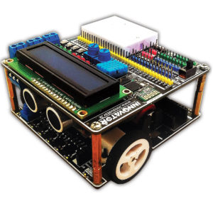
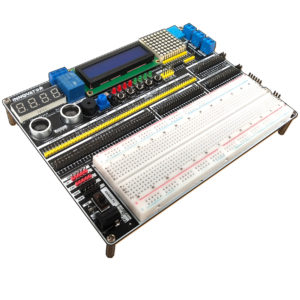

Reviews
There are no reviews yet.