


Description
- description
- Downloads
- examples
- Projects
- Package Includes
Arduino boards (NANO, UNO, MEGA), PIC micro-controllers, Raspberry Pi & Node MCU boards
can be Plugged under the Quadrant.
All pins are exposed on the top side of the Quadrant Board for easy access.
Quadrant contained the most useful sensors/ peripherals which are already powered by user plugged board.
Make your dream Idea to reality in 5 minutes!
Recommended:
Beginners to experts including school, University students, teachers electronics developers,or any tech enthusiast.
Also, highly recommended for schools, universities, institutes, academies as an embedded systems learning platform.
Arduino Nano, UNO, Mega, NodeMCU, PIC Microcontroller, Raspberry PI.
/*
INNOVATOR INTERNATIONAL (PVT)LTD.
https://www.innovator.lk/
--------------------------------------------------------
Development Platform : Quadrant 1.0
(embedded development platform)
--------------------------------------------------------
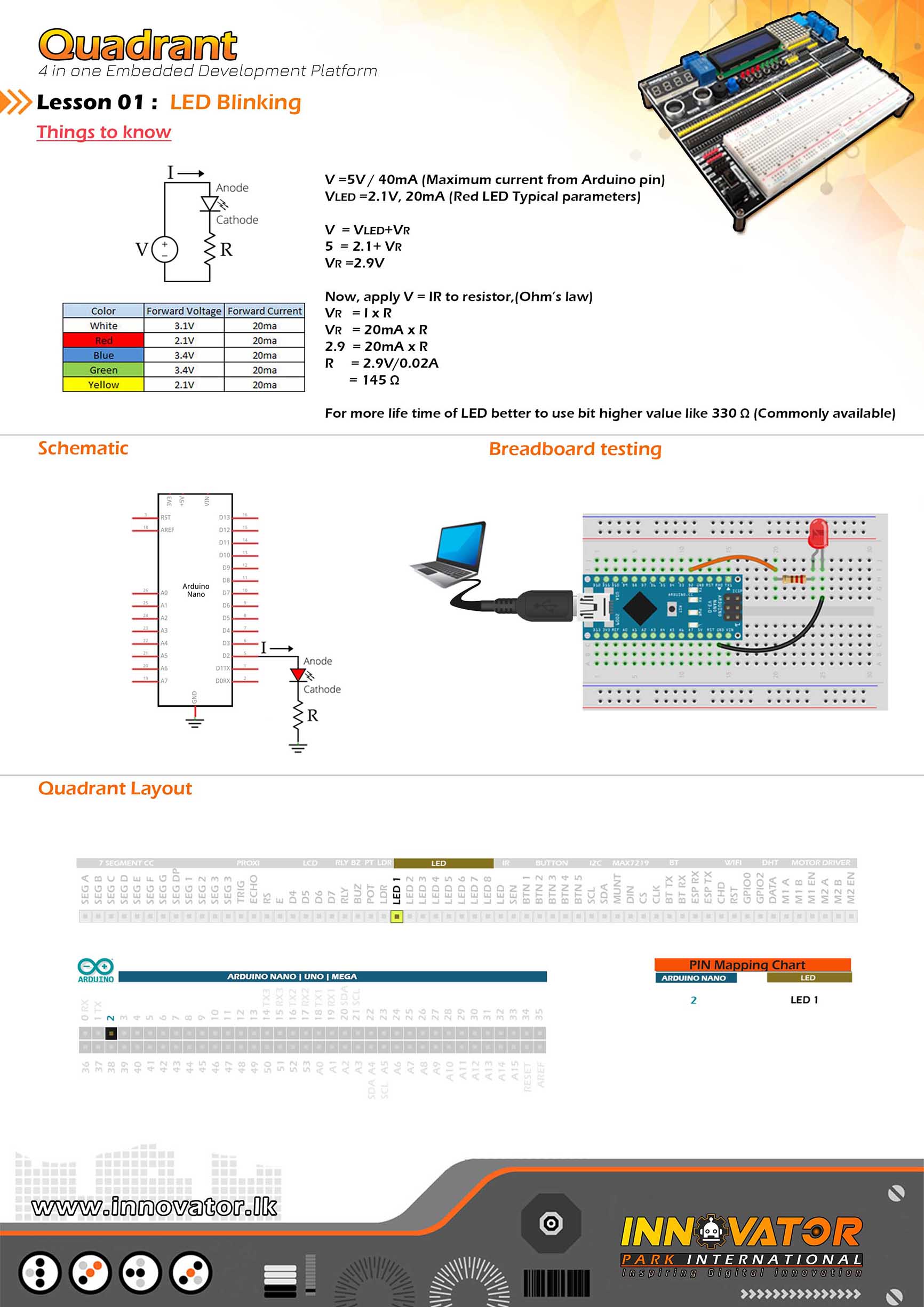
LED Example.
--------------------------------------------------------
Hardware setup :
Connect LED1 PIN to Arduino Digital PIN-> 2(D2)
Connect LED2 PIN to Arduino Digital PIN-> 3(D3)
Connect LED3 PIN to Arduino Digital PIN-> 4(D4)
Connect LED4 PIN to Arduino Digital PIN-> 5(D5)
Connect LED5 PIN to Arduino Digital PIN-> 6(D6)
Connect LED6 PIN to Arduino Digital PIN-> 7(D7)
Connect LED7 PIN to Arduino Digital PIN-> 8(D8)
--------------------------------------------------------
24 march 2021
*/
int LED1 = 2; // the number of the LED1 PIN.
int LED2 = 3; // the number of the LED2 PIN.
int LED3 = 4; // the number of the LED3 PIN.
int LED4 = 5; // the number of the LED4 PIN.
int LED5 = 6; // the number of the LED5 PIN.
int LED6 = 7; // the number of the LED6 PIN.
int LED7 = 8; // the number of the LED7 PIN.
void setup() {
//initializing ALL LED PINs as a output PINs.
pinMode(LED1, OUTPUT);
pinMode(LED2, OUTPUT);
pinMode(LED3, OUTPUT);
pinMode(LED4, OUTPUT);
pinMode(LED5, OUTPUT);
pinMode(LED6, OUTPUT);
pinMode(LED7, OUTPUT);
}
void loop() {
//making all LEDs on
digitalWrite(LED1, HIGH);
digitalWrite(LED2, HIGH);
digitalWrite(LED3, HIGH);
digitalWrite(LED4, HIGH);
digitalWrite(LED5, HIGH);
digitalWrite(LED6, HIGH);
digitalWrite(LED7, HIGH);
delay(1000);//waiting for one second to be elapsed.
//making all LEDs off
digitalWrite(LED1, LOW);
digitalWrite(LED2, LOW);
digitalWrite(LED3, LOW);
digitalWrite(LED4, LOW);
digitalWrite(LED5, LOW);
digitalWrite(LED6, LOW);
digitalWrite(LED7, LOW);
delay(1000);//waiting for one second to be elapsed.
}
/*
INNOVATOR INTERNATIONAL (PVT)LTD.
https://www.innovator.lk/
--------------------------------------------------------
Development Platform : Quadrant 1.0
(embedded development platform)
--------------------------------------------------------
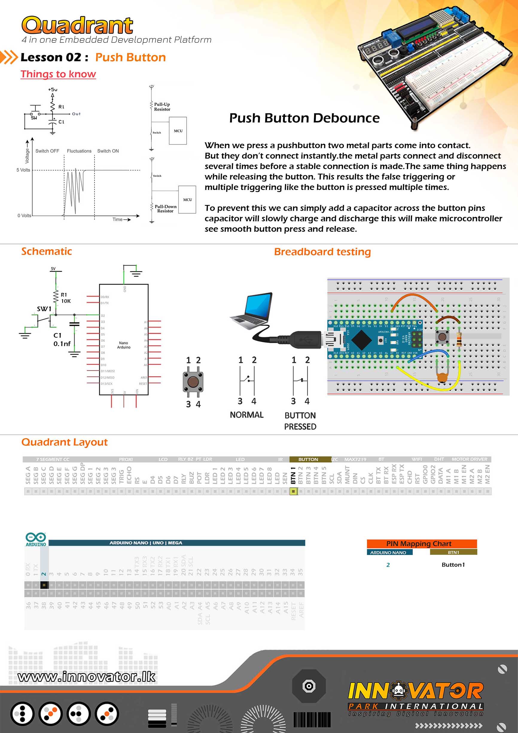
Buttons Example.
--------------------------------------------------------
Hardware setup :
Connect BTN1 PIN to Arduino Digital PIN-> 2(D2)
Connect BTN2 PIN to Arduino Digital PIN-> 3(D3)
Connect BTN3 PIN to Arduino Digital PIN-> 4(D4)
Connect BTN4 PIN to Arduino Digital PIN-> 5(D5)
Connect BTN5 PIN to Arduino Digital PIN-> 6(D6)
--------------------------------------------------------
24 march 2021
*/
int button1 = 2;//PIN number of the push button 1.
int button2 = 3;//PIN number of the push button 2.
int button3 = 4;//PIN number of the push button 3.
int button4 = 5;//PIN number of the push button 4.
int button5 = 6;//PIN number of the push button 5.
//few variables to hold the button state.
boolean b1 = true;
boolean b2 = true;
boolean b3 = true;
boolean b4 = true;
boolean b5 = true;
void setup() {
//initializing ALL button PINs as inputs.
pinMode(button1, INPUT);
pinMode(button2, INPUT);
pinMode(button3, INPUT);
pinMode(button4, INPUT);
pinMode(button5, INPUT);
Serial.begin(9600);//starting serial communication between arduino and computer.
}
void loop() {
//reading all buttons and store states in variables.
boolean b1 = digitalRead(button1);
boolean b2 = digitalRead(button2);
boolean b3 = digitalRead(button3);
boolean b4 = digitalRead(button4);
boolean b5 = digitalRead(button5);
//check variable value if it is "FALSE" and print message to serial monitor.
if (!b1) {
Serial.println("button 1 pressed !");
}
if (!b2) {
Serial.println("button 2 pressed !");
}
if (!b3) {
Serial.println("button 3 pressed !");
}
if (!b4) {
Serial.println("button 4 pressed !");
}
if (!b5) {
Serial.println("button 5 pressed !");
}
}
/*
INNOVATOR INTERNATIONAL (PVT)LTD.
https://www.innovator.lk/
--------------------------------------------------------
Development Platform : Quadrant 1.0
(embedded development platform)
--------------------------------------------------------
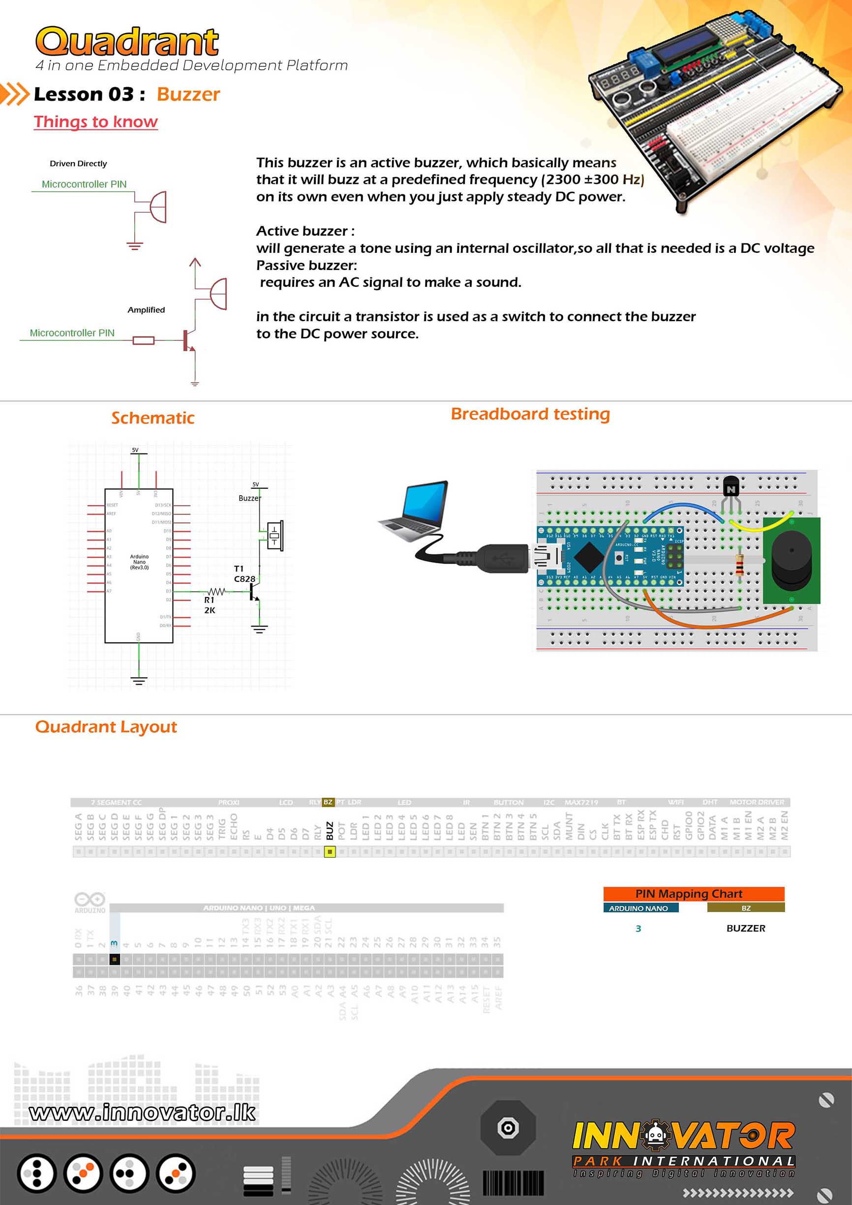
Buzzer Example.
--------------------------------------------------------
Hardware setup :
Connect BUZ PIN to Arduino Digital PIN-> 2(D2)
--------------------------------------------------------
24 march 2021
*/
int BUZZER = 2;// the number of the BUZZER pin.
void setup() {
pinMode(BUZZER, OUTPUT);//initializing BUZZER pin as a output pin.
}
void loop() {
digitalWrite(BUZZER, HIGH);//turning on the BUZZER.
delay(1000);//waiting for one second to be elapsed.
digitalWrite(BUZZER, LOW);//turning off the BUZZER.
delay(1000);//waiting for one second to be elapsed.
}
/*
INNOVATOR INTERNATIONAL (PVT)LTD.
https://www.innovator.lk/
--------------------------------------------------------
Development Platform : Quadrant 1.0
(embedded development platform)
--------------------------------------------------------
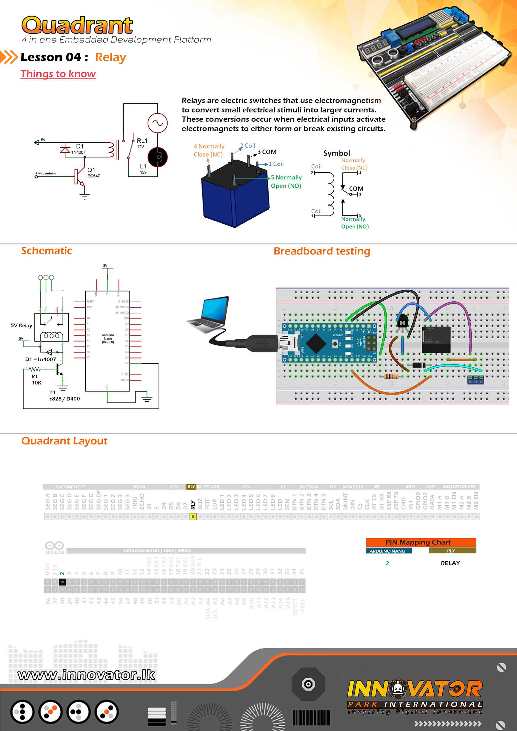
Relay Example.
--------------------------------------------------------
Hardware setup :
Connect RELAY PIN to Arduino digital PIN 2(D2)
--------------------------------------------------------
24 march 2021
*/
int RELAY = 2;// the number of the RELAY pin.
void setup() {
pinMode(RELAY, OUTPUT);//initializing RELAY pin as a output pin.
}
void loop() {
digitalWrite(RELAY, HIGH);//turning on the RELAY.
delay(1000);//waiting for one second to be elapsed.
digitalWrite(RELAY, LOW);//turning off the RELAY.
delay(1000);//waiting for one second to be elapsed.
}
/*
INNOVATOR INTERNATIONAL (PVT)LTD.
--------------------------------------------------------
Development Platform : Quadrant 1.0
(embedded development platform)
--------------------------------------------------------
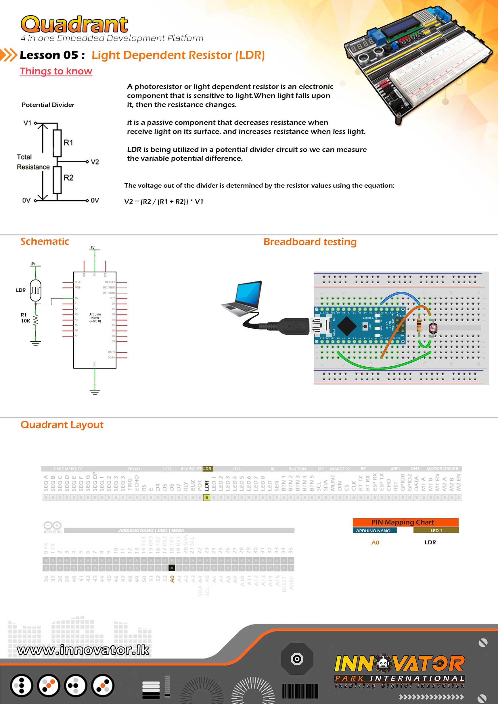
Hardware setup :
connect LDR PIN to Arduino Analog PIN-> 0(A0)
turn on power switch of the top development board.
--------------------------------------------------------
22 march 2021
*/
int LDR = A0;// the number of the LDR pin.
void setup() {
Serial.begin(9600);//starting serial communication between arduino and computer.
pinMode(LDR, INPUT);//initializing LDR pin as a input pin.
}
void loop() {
int LDR_VALUE = analogRead(LDR);//read and store the value of the LDR pin in the variable called "LDR_VALUE".
Serial.println(LDR_VALUE);//printing the value of "LDR_VALUE" variable to the serial monitor.
delay(1000);//waiting for one second to be elapsed.
}
/*
INNOVATOR INTERNATIONAL (PVT)LTD.
https://www.innovator.lk/
--------------------------------------------------------
Development Platform : Quadrant 1.0
(embedded development platform)
--------------------------------------------------------
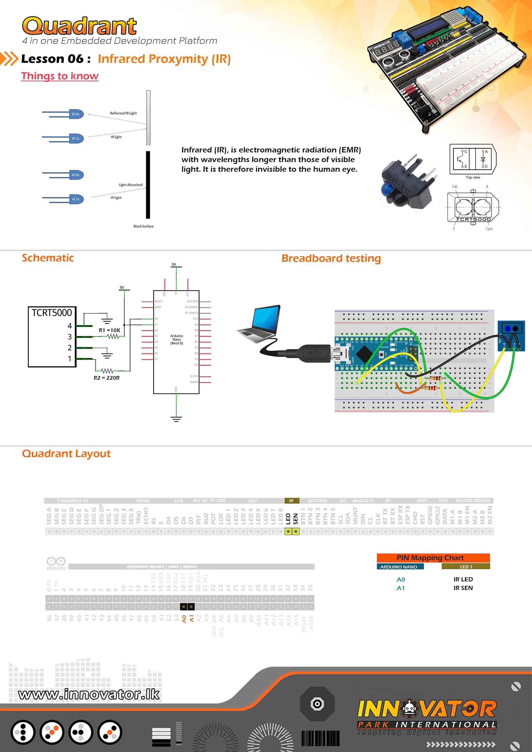
TCRT5000 IR Sensor Example.
--------------------------------------------------------
Hardware setup :
connect IR_LED PIN to Arduino Analog PIN-> 0(A0)
connect IR_SEN PIN to Arduino Analog PIN-> 1(A1)
--------------------------------------------------------
24 march 2021
*/
int IR_Rx = A1;
int IR_Tx = A0;
int value = 0;
void setup() {
pinMode(IR_Tx, OUTPUT);
pinMode(IR_Rx, INPUT);
Serial.begin(9600);
}
void loop() {
value = analogRead(IR_Rx);
digitalWrite(IR_Tx, HIGH);
Serial.println(value);
}
/*
INNOVATOR INTERNATIONAL (PVT)LTD.
https://www.innovator.lk/
--------------------------------------------------------
Development Platform : Quadrant 1.0
(embedded development platform)
--------------------------------------------------------
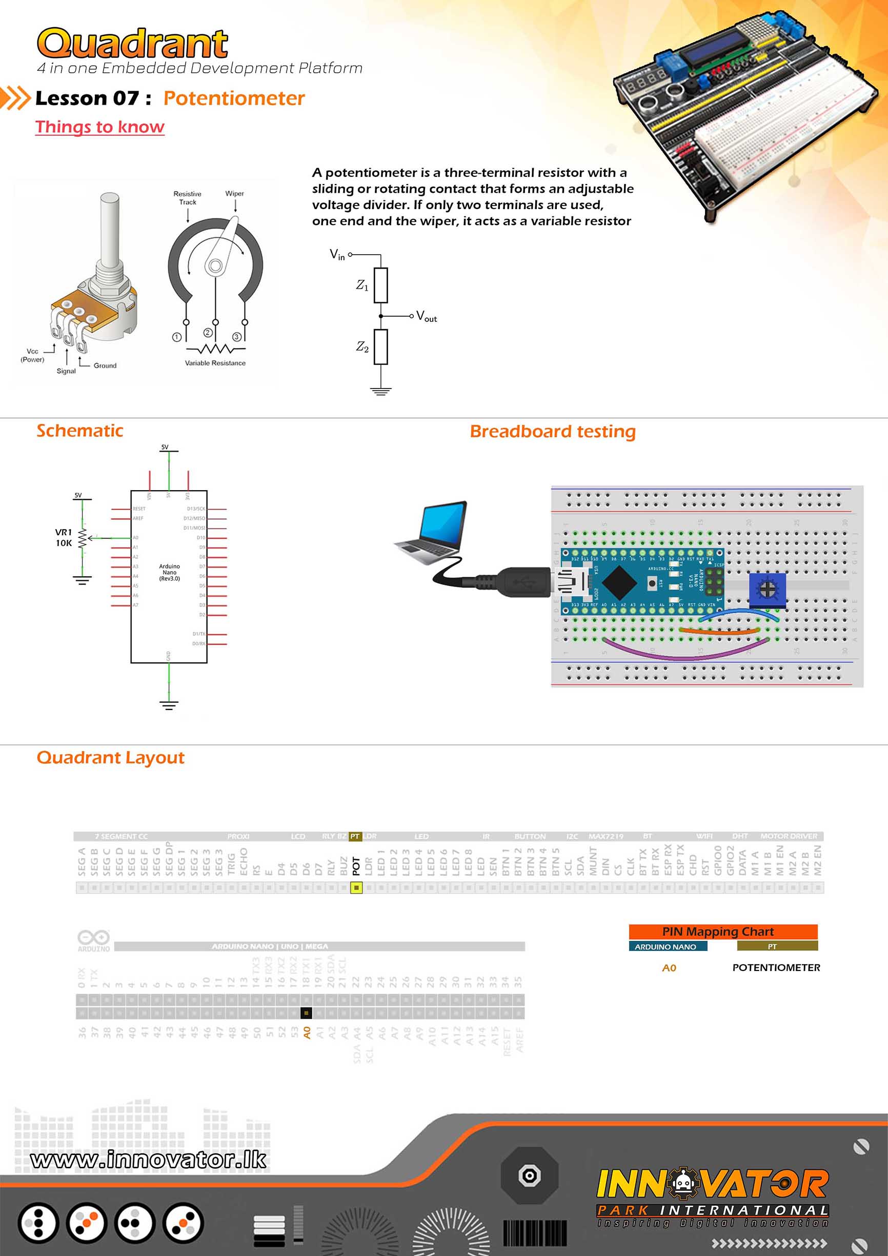
PotentioMeter Example.
--------------------------------------------------------
Hardware setup :
Connect POT to Arduino analog PIN-> 0(A0)
--------------------------------------------------------
24 march 2021
*/
int Potentiometer = A0;//the number of the POT pin.
int value = 0;//a variable to hold the potentiometer value.
void setup() {
pinMode(Potentiometer, INPUT);//initializing POT pin as a input pin.
Serial.begin(9600);//starting serial communication between arduino and computer.
}
void loop() {
value = analogRead(Potentiometer);//read and store the value of the POT pin in the variable called "value".
Serial.println(value);//printing the value of "value" variable to the serial monitor.
delay(1000);//waiting for one second to be elapsed.
}
/*
INNOVATOR INTERNATIONAL (PVT)LTD.
https://www.innovator.lk/
--------------------------------------------------------
Development Platform : Quadrant 1.0
(embedded development platform)
--------------------------------------------------------
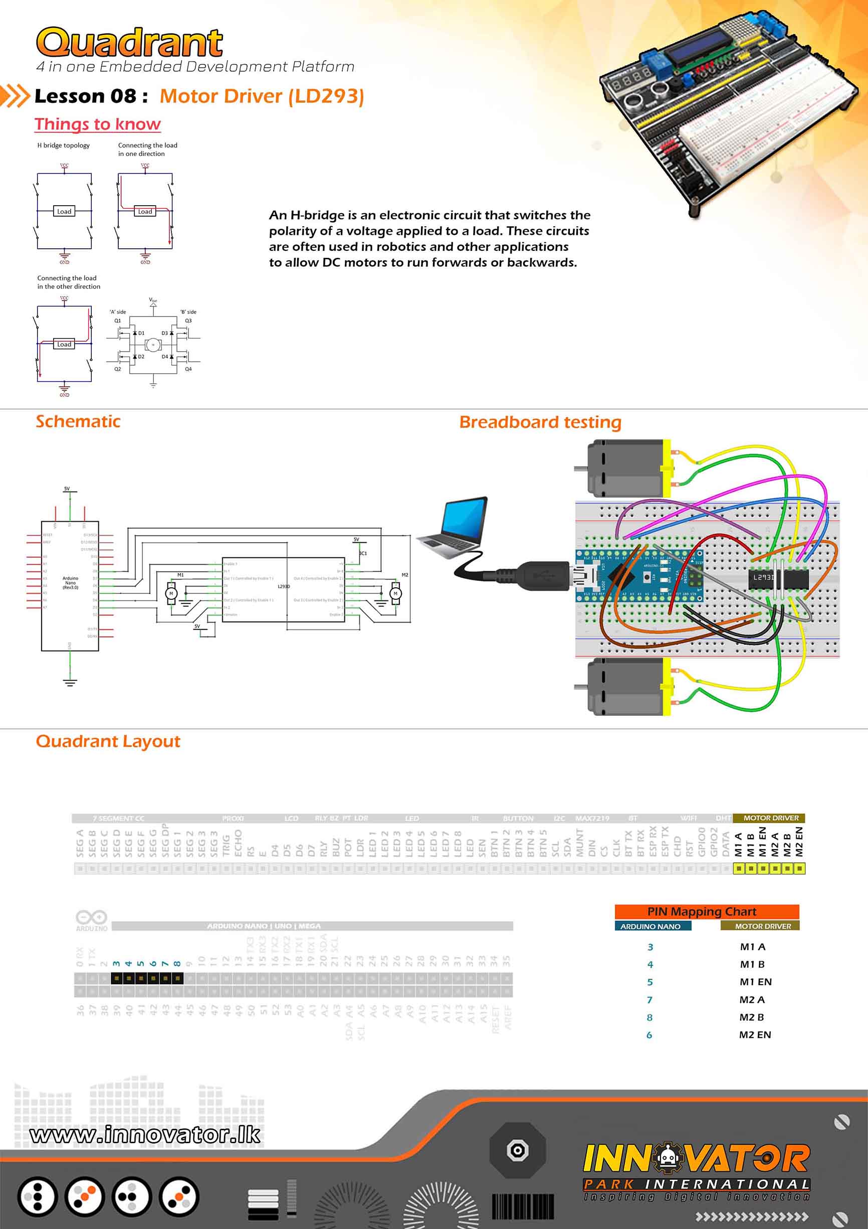
Motor Driver Example.
--------------------------------------------------------
Hardware setup :
// Motor A connections
connect M1_EN to Arduino digital PIN-> 5(D5)
connect M1_A to Arduino digital PIN-> 3(D3)
connect M1_B to Arduino digital PIN-> 4(D4)
// Motor B connections
connect M2_EN to Arduino digital PIN-> 6(D6)
connect M2_A to Arduino Digital PIN-> 7(D7)
connect M2_B to Arduino Digital PIN-> 8(D8)
--------------------------------------------------------
24 march 2021
*/
// Motor A connections
int M1_EN = 5;//the number of the M1_EN pin.
int M1_A = 3;//the number of the M1_A pin.
int M1_B = 4;//the number of the M1_B pin.
// Motor B connections
int M2_EN = 6;//the number of the M2_EN pin.
int M2_A = 7;//the number of the M2_A pin.
int M2_B = 8;//the number of the M2_B pin.
void setup() {
// Set all the motor control pins to outputs
pinMode(M1_EN, OUTPUT);
pinMode(M2_EN, OUTPUT);
pinMode(M1_A, OUTPUT);
pinMode(M1_B, OUTPUT);
pinMode(M2_A, OUTPUT);
pinMode(M2_B, OUTPUT);
// Turn off motors - Initial state
digitalWrite(M1_A, LOW);
digitalWrite(M1_B, LOW);
digitalWrite(M2_A, LOW);
digitalWrite(M2_B, LOW);
}
void loop() {
directionControl();
delay(1000);
speedControl();
delay(1000);
}
// This function lets you control spinning direction of motors
void directionControl() {
// Set motors to maximum speed
// For PWM maximum possible values are 0 to 255
analogWrite(M1_EN, 255);
analogWrite(M2_EN, 255);
// Turn on motor A & B
digitalWrite(M1_A, HIGH);
digitalWrite(M1_B, LOW);
digitalWrite(M2_A, HIGH);
digitalWrite(M2_B, LOW);
delay(2000);
// Now change motor directions
digitalWrite(M1_A, LOW);
digitalWrite(M1_B, HIGH);
digitalWrite(M2_A, LOW);
digitalWrite(M2_B, HIGH);
delay(2000);
// Turn off motors
digitalWrite(M1_A, LOW);
digitalWrite(M1_B, LOW);
digitalWrite(M2_A, LOW);
digitalWrite(M2_B, LOW);
}
// This function lets you control speed of the motors
void speedControl() {
// Turn on motors
digitalWrite(M1_A, LOW);
digitalWrite(M1_B, HIGH);
digitalWrite(M2_A, LOW);
digitalWrite(M2_B, HIGH);
// Accelerate from zero to maximum speed
for (int i = 0; i < 256; i++) { analogWrite(M1_EN, i); analogWrite(M2_EN, i); delay(20); } // Decelerate from maximum speed to zero for (int i = 255; i >= 0; --i) {
analogWrite(M1_EN, i);
analogWrite(M2_EN, i);
delay(20);
}
// Now turn off motors
digitalWrite(M1_A, LOW);
digitalWrite(M1_B, LOW);
digitalWrite(M2_A, LOW);
digitalWrite(M2_B, LOW);
}
/*
INNOVATOR INTERNATIONAL (PVT)LTD.
https://www.innovator.lk/
--------------------------------------------------------
Development Platform : Quadrant 1.0
(embedded development platform)
--------------------------------------------------------
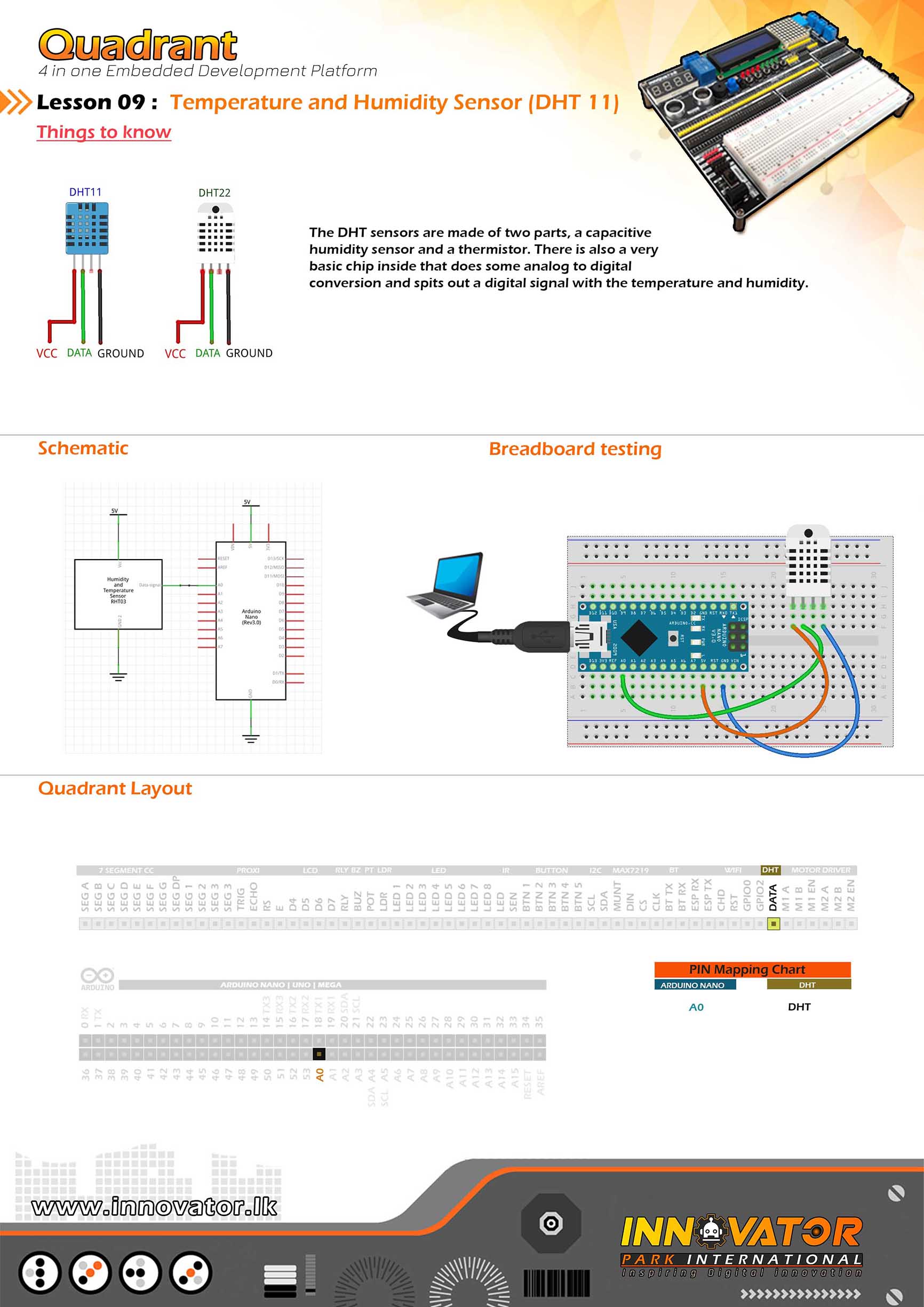
DHT11 Sensor Example.
--------------------------------------------------------
Hardware setup :
connect DHT's DATA PIN to Arduino analog PIN-> 0(A0)
--------------------------------------------------------
24 march 2021
*/
#include "DHT.h";//including the DHT sensor library.
int DHTPIN = A0; // the number of the RELAY pin.
int DHTTYPE = DHT11;// selecting the DHT sensor model.
DHT dht(DHTPIN, DHTTYPE);//initializing DHT object.
float Humidity; // variable to hold the humidity value.
float Temperature;// variable to hold the temperature value.
void setup() {
Serial.begin(9600);//starting serial communication between arduino and computer.
dht.begin(); //initializing connection to the DHT sensor.
}
void loop() {
//read data and store it to variables called "Humidity" and "Temperature".
Humidity = dht.readHumidity();
Temperature = dht.readTemperature();
//printing values to the serial monitor.
Serial.print("Humidity: ");
Serial.print(Humidity);
Serial.print(" %, Temp: ");
Serial.print(Temperature);
Serial.println(" Celsius");
delay(2000);//keep a two second delay between each serial print.
}
/*
/*
INNOVATOR INTERNATIONAL (PVT)LTD.
https://www.innovator.lk/
----------------------------------------------------------------------
Development Platform : Quadrant 1.0
(embedded development platform)
----------------------------------------------------------------------
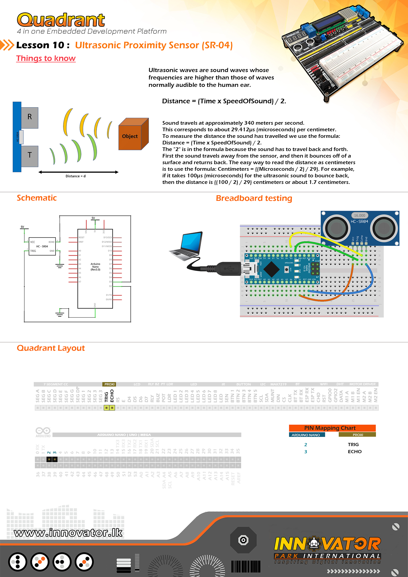
hc-sr04 Ultrasonic Distance Sensor Example.
----------------------------------------------------------------------
Hardware setup :
connect ECHO PIN of the HC-SR04 module to Arduino digital PIN 2(D2)
connect TRIG PIN of the HC-SR04 module to Arduino digital PIN 3(D3)
----------------------------------------------------------------------
24 march 2021
*/
int TRIG = 2;// the number of the ECHO pin.
int ECHO = 3;// the number of the TRIG pin.
long duration; // variable to hold the duration of sound wave travel value.
int distance; // variable to hold the distance measurement value.
void setup() {
pinMode(TRIG, OUTPUT); //initializing TRIG pin as a output pin.
pinMode(ECHO, INPUT); //initializing ECHO pin as a input pin.
Serial.begin(9600); //starting serial communication between arduino and computer.
}
void loop() {
// making the TRIG pin LOW for 2 microseconds.
digitalWrite(TRIG, LOW);
delayMicroseconds(2);
// making the TRIG pin HIGH for 10 microseconds.
digitalWrite(TRIG, HIGH);
delayMicroseconds(10);
digitalWrite(TRIG, LOW);
// reads the ECHO pin value and returns the sound wave travel time in microseconds.
duration = pulseIn(ECHO, HIGH);
// calculating the distance.
distance = duration * 0.034 / 2; // speed of sound wave divided by 2 (to go forward and reflect on something and come back).
// displays the calculated distance in the serial monitor.
Serial.print("Distance: ");
Serial.print(distance);
Serial.println(" cm");
}
/*
INNOVATOR INTERNATIONAL (PVT)LTD.
https://www.innovator.lk/
------------------------------------------------------------
Development Platform : Quadrant 1.0
(embedded development platform)
------------------------------------------------------------
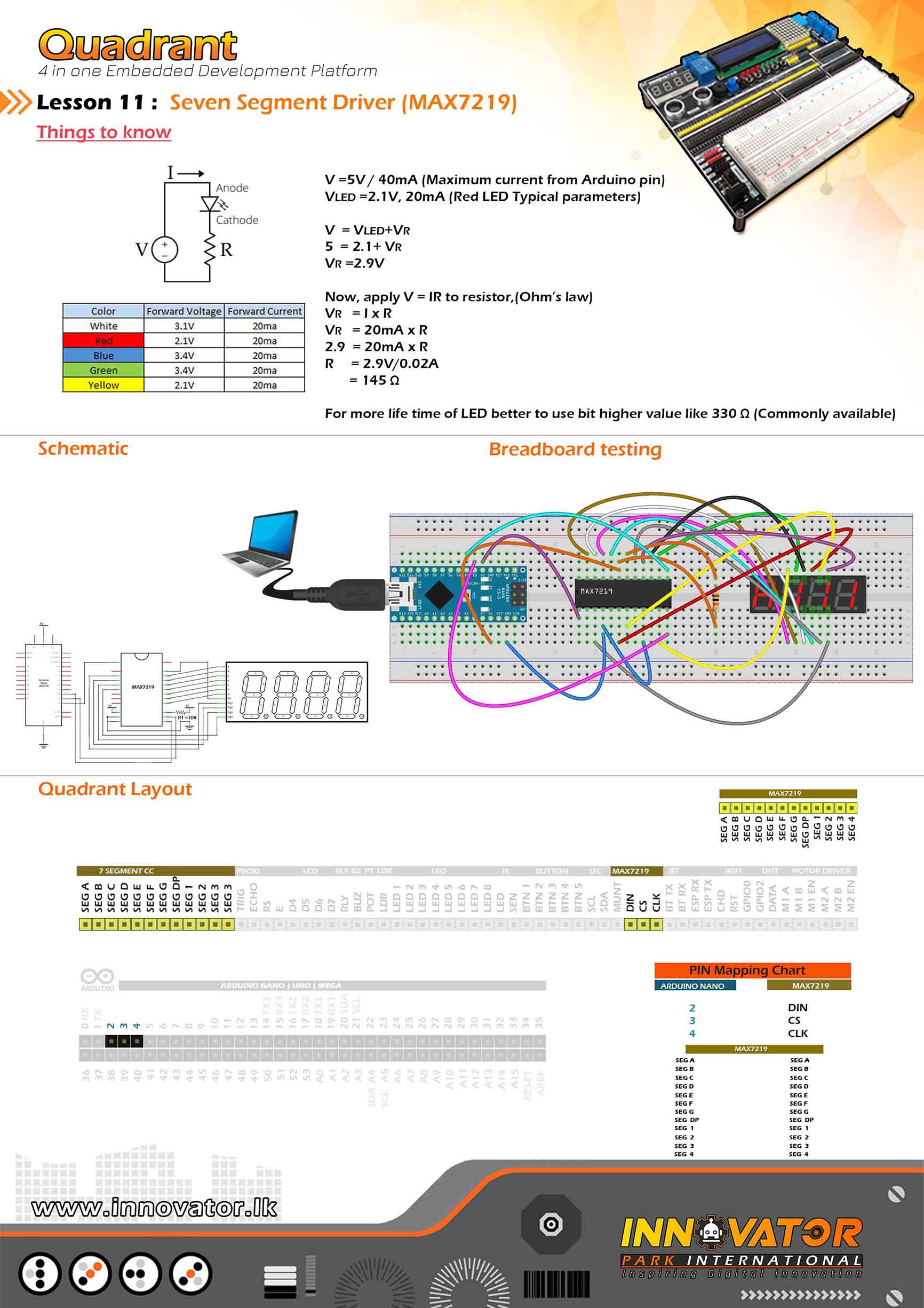
MAX7219 4Digit Seven Segment Display Example.
------------------------------------------------------------
Hardware setup :
Hardware setup :
Connect "7 Segment[cc]" PINs near dotmatrix to the PINs
of "7 Segment[cc]" beleow the 4digit seven segment display.
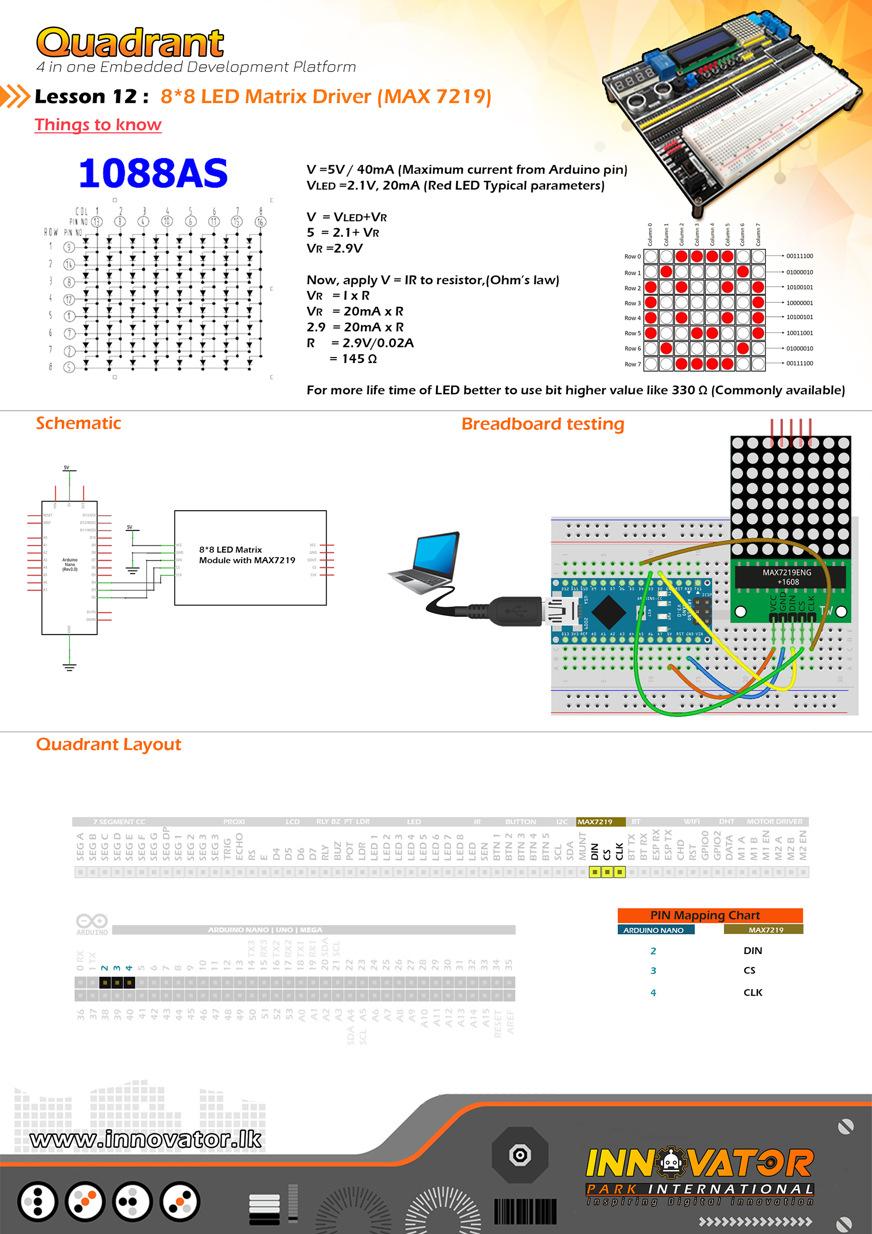
connect MAX7219 DIN PIN to Arduino digital PIN 2(D2).
connect MAX7219 CS PIN to Arduino digital PIN 3(D3).
connect MAX7219 CLK PIN to Arduino digital PIN 4(D4).
------------------------------------------------------------
24 march 2021
*/
#include "LedControl.h" // library for LED control with MAX7219.
int DIN = 2;
int CLK = 3;
int CS = 4;
LedControl lc = LedControl(DIN, CLK, CS, 1); //DIN | CLK | CS | number of matrices.
void setup() {
lc.shutdown(0, false); // the MAX7219 is in power-saving mode on startup, we have to do a wakeup call.
lc.setIntensity(0, 15); // set the brightness of display between 0 and 15.
lc.clearDisplay(0); // clear the display.
lc.setDigit(0, 3, 0, false);
lc.setDigit(0, 2, 0, false);
lc.setDigit(0, 1, 0, true);
lc.setDigit(0, 0, 0, false);
}
void loop() {
lc.setDigit(0, 3, 1, true);
lc.setDigit(0, 2, 1, false);
lc.setDigit(0, 1, 3, true);
lc.setDigit(0, 0, 3, false);
}
/*
  INNOVATOR INTERNATIONAL (PVT)LTD.
  https://www.innovator.lk/
  --------------------------------------------------------
  Development Platform : Quadrant 1.0
  (embedded development platform)
  --------------------------------------------------------
  MAX7219 Scroll Example.
  --------------------------------------------------------
  Connect MAX7219  DIN PIN to Arduino digital PIN 2(D2).
  Connect MAX7219  CS   PIN to Arduino digital PIN 3(D3).
  Connect MAX7219  CLK  PIN to Arduino digital PIN 4(D4).
  --------------------------------------------------------
  24 march 2021
*/

#include "LedControl.h"
const int numDevices = 1;      //number of MAX7219s
const long scrollDelay = 100;   //scrolling speed
unsigned long bufferLong [14] = {0};

int DIN = 2;
int CLK = 4;
int CS = 3;

LedControl lc = LedControl(DIN, CLK, CS, numDevices); //DIN | CLK | CS | number of matrices

const unsigned char scrollText[] PROGMEM = {" INNOVATOR 2021 "}; // text to be scrolled.

void setup()
{
  for (int x = 0; x < numDevices; x++)
  {
    lc.shutdown(x, false);      //The MAX72XX is in power-saving mode on startup
    lc.setIntensity(x, 8);      // Set the brightness to default value
    lc.clearDisplay(x);         // and clear the display
  }
}

void loop() {
  scrollMessage(scrollText);
}

///////////////////////////////////////////////////////////////////////////////////////////////////////////////////

const unsigned char font5x7 [] PROGMEM = {      //Numeric Font Matrix (Arranged as 7x font DIN + 1x kerning DIN)
  B00000000,  //Space (Char 0x20)
  B00000000,
  B00000000,
  B00000000,
  B00000000,
  B00000000,
  B00000000,
  3,

  B01000000,  //!
  B01000000,
  B01000000,
  B01000000,
  B01000000,
  B00000000,
  B01000000,
  2,

  B10100000,  //"
  B10100000,
  B10100000,
  B00000000,
  B00000000,
  B00000000,
  B00000000,
  4,

  B01010000,  //#
  B01010000,
  B11111000,
  B01010000,
  B11111000,
  B01010000,
  B01010000,
  6,

  B00100000,  //$
  B01111000,
  B10100000,
  B01110000,
  B00101000,
  B11110000,
  B00100000,
  6,

  B11000000,  //%
  B11001000,
  B00010000,
  B00100000,
  B01000000,
  B10011000,
  B00011000,
  6,

  B01100000,  //&
  B10010000,
  B10100000,
  B01000000,
  B10101000,
  B10010000,
  B01101000,
  6,

  B11000000,  //'
  B01000000,
  B10000000,
  B00000000,
  B00000000,
  B00000000,
  B00000000,
  3,

  B00100000,  //(
  B01000000,
  B10000000,
  B10000000,
  B10000000,
  B01000000,
  B00100000,
  4,

  B10000000,  //)
  B01000000,
  B00100000,
  B00100000,
  B00100000,
  B01000000,
  B10000000,
  4,

  B00000000,  //*
  B00100000,
  B10101000,
  B01110000,
  B10101000,
  B00100000,
  B00000000,
  6,

  B00000000,  //+
  B00100000,
  B00100000,
  B11111000,
  B00100000,
  B00100000,
  B00000000,
  6,

  B00000000,  //,
  B00000000,
  B00000000,
  B00000000,
  B11000000,
  B01000000,
  B10000000,
  3,

  B00000000,  //-
  B00000000,
  B11111000,
  B00000000,
  B00000000,
  B00000000,
  B00000000,
  6,

  B00000000,  //.
  B00000000,
  B00000000,
  B00000000,
  B00000000,
  B11000000,
  B11000000,
  3,

  B00000000,  ///
  B00001000,
  B00010000,
  B00100000,
  B01000000,
  B10000000,
  B00000000,
  6,

  B01110000,  //0
  B10001000,
  B10011000,
  B10101000,
  B11001000,
  B10001000,
  B01110000,
  6,

  B01000000,  //1
  B11000000,
  B01000000,
  B01000000,
  B01000000,
  B01000000,
  B11100000,
  4,

  B01110000,  //2
  B10001000,
  B00001000,
  B00010000,
  B00100000,
  B01000000,
  B11111000,
  6,

  B11111000,  //3
  B00010000,
  B00100000,
  B00010000,
  B00001000,
  B10001000,
  B01110000,
  6,

  B00010000,  //4
  B00110000,
  B01010000,
  B10010000,
  B11111000,
  B00010000,
  B00010000,
  6,

  B11111000,  //5
  B10000000,
  B11110000,
  B00001000,

  B00001000,
  B10001000,
  B01110000,
  6,

  B00110000,  //6
  B01000000,
  B10000000,
  B11110000,
  B10001000,
  B10001000,
  B01110000,
  6,

  B11111000,  //7
  B10001000,
  B00001000,
  B00010000,
  B00100000,
  B00100000,
  B00100000,
  6,

  B01110000,  //8
  B10001000,
  B10001000,
  B01110000,
  B10001000,
  B10001000,
  B01110000,
  6,

  B01110000,  //9
  B10001000,
  B10001000,
  B01111000,
  B00001000,
  B00010000,
  B01100000,
  6,

  B00000000,  //:
  B11000000,
  B11000000,
  B00000000,
  B11000000,
  B11000000,
  B00000000,
  3,

  B00000000,  //;
  B11000000,
  B11000000,
  B00000000,
  B11000000,
  B01000000,
  B10000000,
  3,

  B00010000,  //< B00100000, B01000000, B10000000, B01000000, B00100000, B00010000, 5, B00000000, //= B00000000, B11111000, B00000000, B11111000, B00000000, B00000000, 6, B10000000, //>
  B01000000,
  B00100000,
  B00010000,
  B00100000,
  B01000000,
  B10000000,
  5,

  B01110000,  //?
  B10001000,
  B00001000,
  B00010000,
  B00100000,
  B00000000,
  B00100000,
  6,

  B01110000,  //@
  B10001000,
  B00001000,
  B01101000,
  B10101000,
  B10101000,
  B01110000,
  6,

  B01110000,  //A
  B10001000,
  B10001000,
  B10001000,
  B11111000,
  B10001000,
  B10001000,
  6,

  B11110000,  //B
  B10001000,
  B10001000,
  B11110000,
  B10001000,
  B10001000,
  B11110000,
  6,

  B01110000,  //C
  B10001000,
  B10000000,
  B10000000,
  B10000000,
  B10001000,
  B01110000,
  6,

  B11100000,  //D
  B10010000,
  B10001000,
  B10001000,
  B10001000,
  B10010000,
  B11100000,
  6,

  B11111000,  //E
  B10000000,
  B10000000,
  B11110000,
  B10000000,
  B10000000,
  B11111000,
  6,

  B11111000,  //F
  B10000000,
  B10000000,
  B11110000,
  B10000000,
  B10000000,
  B10000000,
  6,

  B01110000,  //G
  B10001000,
  B10000000,
  B10111000,
  B10001000,
  B10001000,
  B01111000,
  6,

  B10001000,  //H
  B10001000,
  B10001000,
  B11111000,
  B10001000,
  B10001000,
  B10001000,
  6,

  B11100000,  //I
  B01000000,
  B01000000,
  B01000000,
  B01000000,
  B01000000,
  B11100000,
  4,

  B00111000,  //J
  B00010000,
  B00010000,
  B00010000,
  B00010000,
  B10010000,
  B01100000,
  6,

  B10001000,  //K
  B10010000,
  B10100000,
  B11000000,
  B10100000,
  B10010000,
  B10001000,
  6,

  B10000000,  //L
  B10000000,
  B10000000,
  B10000000,
  B10000000,
  B10000000,
  B11111000,
  6,

  B10001000,  //M
  B11011000,
  B10101000,
  B10101000,
  B10001000,
  B10001000,
  B10001000,
  6,

  B10001000,  //N
  B10001000,
  B11001000,
  B10101000,
  B10011000,
  B10001000,
  B10001000,
  6,

  B01110000,  //O
  B10001000,
  B10001000,
  B10001000,
  B10001000,
  B10001000,
  B01110000,
  6,

  B11110000,  //P
  B10001000,
  B10001000,
  B11110000,
  B10000000,
  B10000000,
  B10000000,
  6,

  B01110000,  //Q
  B10001000,
  B10001000,
  B10001000,
  B10101000,
  B10010000,
  B01101000,
  6,

  B11110000,  //R
  B10001000,
  B10001000,
  B11110000,
  B10100000,
  B10010000,
  B10001000,
  6,

  B01111000,  //S
  B10000000,
  B10000000,
  B01110000,
  B00001000,
  B00001000,
  B11110000,
  6,

  B11111000,  //T
  B00100000,
  B00100000,
  B00100000,
  B00100000,
  B00100000,
  B00100000,
  6,

  B10001000,  //U
  B10001000,
  B10001000,
  B10001000,
  B10001000,
  B10001000,

  B01110000,
  6,

  B10001000,  //V
  B10001000,
  B10001000,
  B10001000,
  B10001000,
  B01010000,
  B00100000,
  6,

  B10001000,  //W
  B10001000,
  B10001000,
  B10101000,
  B10101000,
  B10101000,
  B01010000,
  6,

  B10001000,  //X
  B10001000,
  B01010000,
  B00100000,
  B01010000,
  B10001000,
  B10001000,
  6,

  B10001000,  //Y
  B10001000,
  B10001000,
  B01010000,
  B00100000,
  B00100000,
  B00100000,
  6,

  B11111000,  //Z
  B00001000,
  B00010000,
  B00100000,
  B01000000,
  B10000000,
  B11111000,
  6,

  B11100000,  //[
  B10000000,
  B10000000,
  B10000000,
  B10000000,
  B10000000,
  B11100000,
  4,

  B00000000,  //(Backward Slash)
  B10000000,
  B01000000,
  B00100000,
  B00010000,
  B00001000,
  B00000000,
  6,

  B11100000,  //]
  B00100000,
  B00100000,
  B00100000,
  B00100000,
  B00100000,
  B11100000,
  4,

  B00100000,  //^
  B01010000,
  B10001000,
  B00000000,
  B00000000,
  B00000000,
  B00000000,
  6,

  B00000000,  //_
  B00000000,
  B00000000,
  B00000000,
  B00000000,
  B00000000,
  B11111000,
  6,

  B10000000,  //`
  B01000000,
  B00100000,
  B00000000,
  B00000000,
  B00000000,
  B00000000,
  4,

  B00000000,  //a
  B00000000,
  B01110000,
  B00001000,
  B01111000,
  B10001000,
  B01111000,
  6,

  B10000000,  //b
  B10000000,
  B10110000,
  B11001000,
  B10001000,
  B10001000,
  B11110000,
  6,

  B00000000,  //c
  B00000000,
  B01110000,
  B10001000,
  B10000000,
  B10001000,
  B01110000,
  6,

  B00001000,  //d
  B00001000,
  B01101000,
  B10011000,
  B10001000,
  B10001000,
  B01111000,
  6,

  B00000000,  //e
  B00000000,
  B01110000,
  B10001000,
  B11111000,
  B10000000,
  B01110000,
  6,

  B00110000,  //f
  B01001000,
  B01000000,
  B11100000,
  B01000000,
  B01000000,
  B01000000,
  6,

  B00000000,  //g
  B01111000,
  B10001000,
  B10001000,
  B01111000,
  B00001000,
  B01110000,
  6,

  B10000000,  //h
  B10000000,
  B10110000,
  B11001000,
  B10001000,
  B10001000,
  B10001000,
  6,

  B01000000,  //i
  B00000000,
  B11000000,
  B01000000,
  B01000000,
  B01000000,
  B11100000,
  4,

  B00010000,  //j
  B00000000,
  B00110000,
  B00010000,
  B00010000,
  B10010000,
  B01100000,
  5,

  B10000000,  //k
  B10000000,
  B10010000,
  B10100000,
  B11000000,
  B10100000,
  B10010000,
  5,

  B11000000,  //l
  B01000000,
  B01000000,
  B01000000,
  B01000000,
  B01000000,
  B11100000,
  4,

  B00000000,  //m
  B00000000,
  B11010000,
  B10101000,
  B10101000,
  B10001000,
  B10001000,
  6,

  B00000000,  //n
  B00000000,
  B10110000,
  B11001000,
  B10001000,
  B10001000,
  B10001000,
  6,

  B00000000,  //o
  B00000000,
  B01110000,
  B10001000,
  B10001000,
  B10001000,
  B01110000,
  6,

  B00000000,  //p
  B00000000,
  B11110000,
  B10001000,
  B11110000,
  B10000000,
  B10000000,
  6,

  B00000000,  //q
  B00000000,
  B01101000,
  B10011000,
  B01111000,
  B00001000,
  B00001000,
  6,

  B00000000,  //r
  B00000000,
  B10110000,
  B11001000,
  B10000000,
  B10000000,
  B10000000,
  6,

  B00000000,  //s
  B00000000,
  B01110000,
  B10000000,
  B01110000,
  B00001000,
  B11110000,
  6,

  B01000000,  //t
  B01000000,
  B11100000,
  B01000000,
  B01000000,
  B01001000,
  B00110000,
  6,

  B00000000,  //u
  B00000000,
  B10001000,
  B10001000,
  B10001000,
  B10011000,
  B01101000,
  6,

  B00000000,  //v
  B00000000,
  B10001000,
  B10001000,
  B10001000,
  B01010000,
  B00100000,
  6,

  B00000000,  //w
  B00000000,
  B10001000,
  B10101000,
  B10101000,
  B10101000,
  B01010000,
  6,

  B00000000,  //x
  B00000000,
  B10001000,
  B01010000,
  B00100000,
  B01010000,
  B10001000,
  6,

  B00000000,  //y
  B00000000,
  B10001000,
  B10001000,
  B01111000,
  B00001000,
  B01110000,
  6,

  B00000000,  //z
  B00000000,
  B11111000,
  B00010000,
  B00100000,
  B01000000,
  B11111000,
  6,

  B00100000,  //{
  B01000000,
  B01000000,
  B10000000,
  B01000000,
  B01000000,
  B00100000,
  4,

  B10000000,  //|
  B10000000,
  B10000000,
  B10000000,
  B10000000,
  B10000000,
  B10000000,
  2,

  B10000000,  //}
  B01000000,
  B01000000,
  B00100000,
  B01000000,
  B01000000,
  B10000000,
  4,

  B00000000,  //~
  B00000000,
  B00000000,
  B01101000,
  B10010000,
  B00000000,
  B00000000,
  6,

  B01100000,  // (Char 0x7F)
  B10010000,
  B10010000,
  B01100000,
  B00000000,
  B00000000,
  B00000000,
  5,

  B00000000,  // smiley
  B01100000,
  B01100110,
  B00000000,
  B10000001,
  B01100110,
  B00011000,
  5
};

// Scroll Message
void scrollMessage(const unsigned char * messageString) {
  int counter = 0;
  int myChar = 0;
  do {
    // read back a char
    myChar =  pgm_read_byte_near(messageString + counter);
    if (myChar != 0) {
      loadBufferLong(myChar);
    }
    counter++;
  }
  while (myChar != 0);
}
// Load character into scroll buffer
void loadBufferLong(int ascii) {
  if (ascii >= 0x20 && ascii <= 0x7f) {
    for (int a = 0; a < 7; a++) {               // Loop 7 times for a 5x7 font
      unsigned long c = pgm_read_byte_near(font5x7 + ((ascii - 0x20) * 8) + a);     // Index into character table to get row DIN
      unsigned long x = bufferLong [a * 2];   // Load current scroll buffer
      x = x | c;                              // OR the new character onto end of current
      bufferLong [a * 2] = x;                 // Store in buffer
    }
    byte count = pgm_read_byte_near(font5x7 + ((ascii - 0x20) * 8) + 7);    // Index into character table for kerning DIN
    for (byte x = 0; x < count; x++) {
      rotateBufferLong();
      printBufferLong();
      delay(scrollDelay);
    }
  }
}
// Rotate the buffer
void rotateBufferLong() {
  for (int a = 0; a < 7; a++) {               // Loop 7 times for a 5x7 font
    unsigned long x = bufferLong [a * 2];   // Get low buffer entry
    byte b = bitRead(x, 31);                // Copy high order bit that gets lost in rotation
    x = x << 1;                             // Rotate left one bit
    bufferLong [a * 2] = x;                 // Store new low buffer
    x = bufferLong [a * 2 + 1];             // Get high buffer entry
    x = x << 1;                             // Rotate left one bit
    bitWrite(x, 0, b);                      // Store saved bit
    bufferLong [a * 2 + 1] = x;             // Store new high buffer
  }
}
// Display Buffer on LED matrix
void printBufferLong() {
  for (int a = 0; a < 7; a++) { // Loop 7 times for a 5x7 font unsigned long x = bufferLong [a * 2 + 1]; // Get high buffer entry byte y = x; // Mask off first character lc.setRow(3, a, y); // Send row to relevent MAX7219 chip x = bufferLong [a * 2]; // Get low buffer entry y = (x >> 24);                          // Mask off second character
    lc.setRow(2, a, y);                     // Send row to relevent MAX7219 chip
    y = (x >> 16);                          // Mask off third character
    lc.setRow(1, a, y);                     // Send row to relevent MAX7219 chip
    y = (x >> 8);                           // Mask off forth character
    lc.setRow(0, a, y);                     // Send row to relevent MAX7219 chip
  }
}
/*
INNOVATOR INTERNATIONAL (PVT)LTD.
https://www.innovator.lk/
--------------------------------------------------------
Development Platform : Quadrant 1.0
(embedded development platform)
--------------------------------------------------------
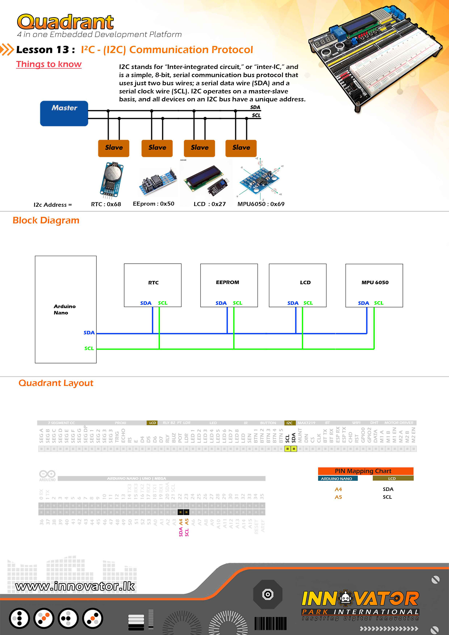
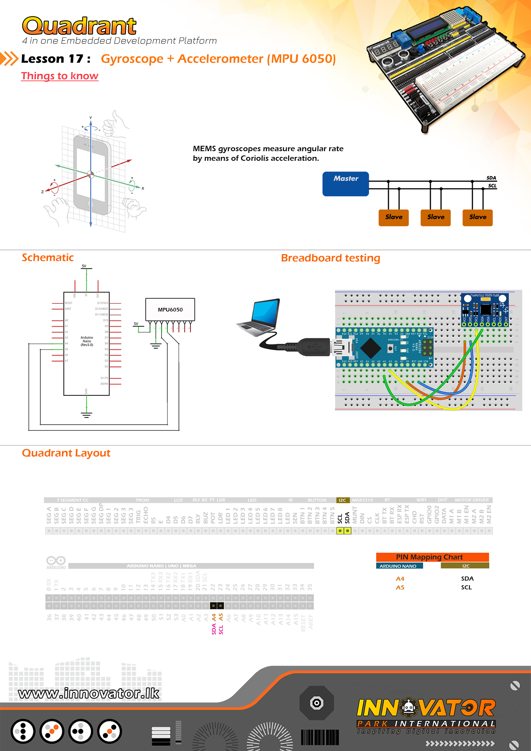
I2C Example.
--------------------------------------------------------
Hardware setup :
Connect Arduino analog PIN 4(A4) to I2C SDA PIN
Connect Arduino analog PIN 5(A5) TO I2C SCL PIN
--------------------------------------------------------
I2C device at address 0x27 = 16*2 LCD
I2C device at address 0x50 = EEPROM
I2C device at address 0x68 = 1307 RTC
I2C device at address 0x68 = MPU6050
--------------------------------------------------------
24 march 2021
*/
#include "Wire.h" // including the wire library in order to communicate with i2c bus devices.
void setup()
{
Wire.begin(); //initializing connection to the i2c device(s).
Serial.begin(9600); //starting serial communication between arduino and computer.
Serial.println("nI2C Scanner"); //printing message to serial print.
}
void loop()
{
byte error, address; // variables to hold the error values and i2c devices addresses.
int nDevices;//varible to hold the i2c device count.
Serial.println("Scanning...");//printing message to seriak print.
nDevices = 0;
for (address = 1; address < 127; address++ )
{
// The i2c_scanner uses the return value of
// the Write.endTransmisstion to see if
// a device did acknowledge to the address.
Wire.beginTransmission(address);
error = Wire.endTransmission();
if (error == 0)
{
Serial.print("I2C device found at address 0x");
if (address < 16)
Serial.print("0");
Serial.print(address, HEX);
Serial.println(" !");
nDevices++;
}
else if (error == 4)
{
Serial.print("Unknown error at address 0x");
if (address < 16)
Serial.print("0");
Serial.println(address, HEX);
}
}
if (nDevices == 0)
Serial.println("No I2C devices foundn");
else
Serial.println("donen");
delay(5000); // wait 5 seconds between each next scan.
}
/*
INNOVATOR INTERNATIONAL (PVT)LTD.
https://www.innovator.lk/
--------------------------------------------------------
Development Platform : Quadrant 1.0
(embedded development platform)
--------------------------------------------------------
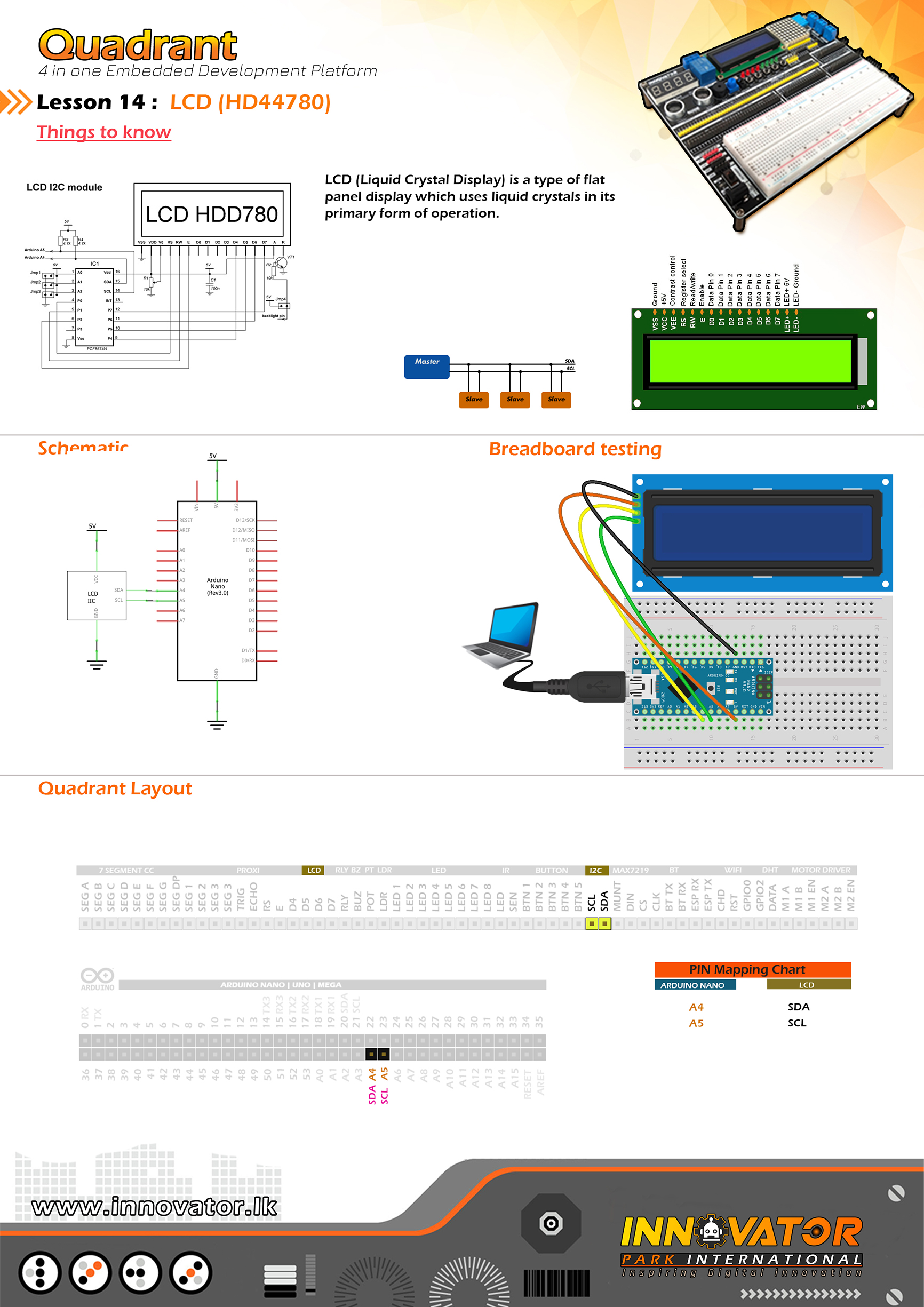
HD44780 16*2 LCD Example.
--------------------------------------------------------
connect Arduino analog PIN 4(A4) to SDA
connect Arduino analog PIN 4(A5) to SCL
--------------------------------------------------------
23 march 2021
*/
#include "LiquidCrystal_I2C.h"//including the LCD driver library.
LiquidCrystal_I2C lcd(0x27, 16, 2);//initializing the LCD I2C address(0x27) and LCD's number of columns(16) and rows(2).
void setup() {
lcd.begin();//initializing connection to the LCD.
lcd.backlight();//turning on the backlight of the LCD.
lcd.setCursor(0, 0);//setting the cursor position to column 0 and row 0.
lcd.print("Quadrant");//printing a message to LCD.
delay(1000);//waiting for one second to be elapsed.
lcd.clear();//clearing the charcters printedd on the LCD.
}
void loop() {
lcd.setCursor(2, 0);//setting the cursor position to column 2 and row 0.
lcd.print("Hello world !");//printing a message to LCD.
}
/*
INNOVATOR INTERNATIONAL (PVT)LTD.
https://www.innovator.lk/
------------------------------------------------------------------
Development Platform : Quadrant 1.0
(embedded development platform)
------------------------------------------------------------------
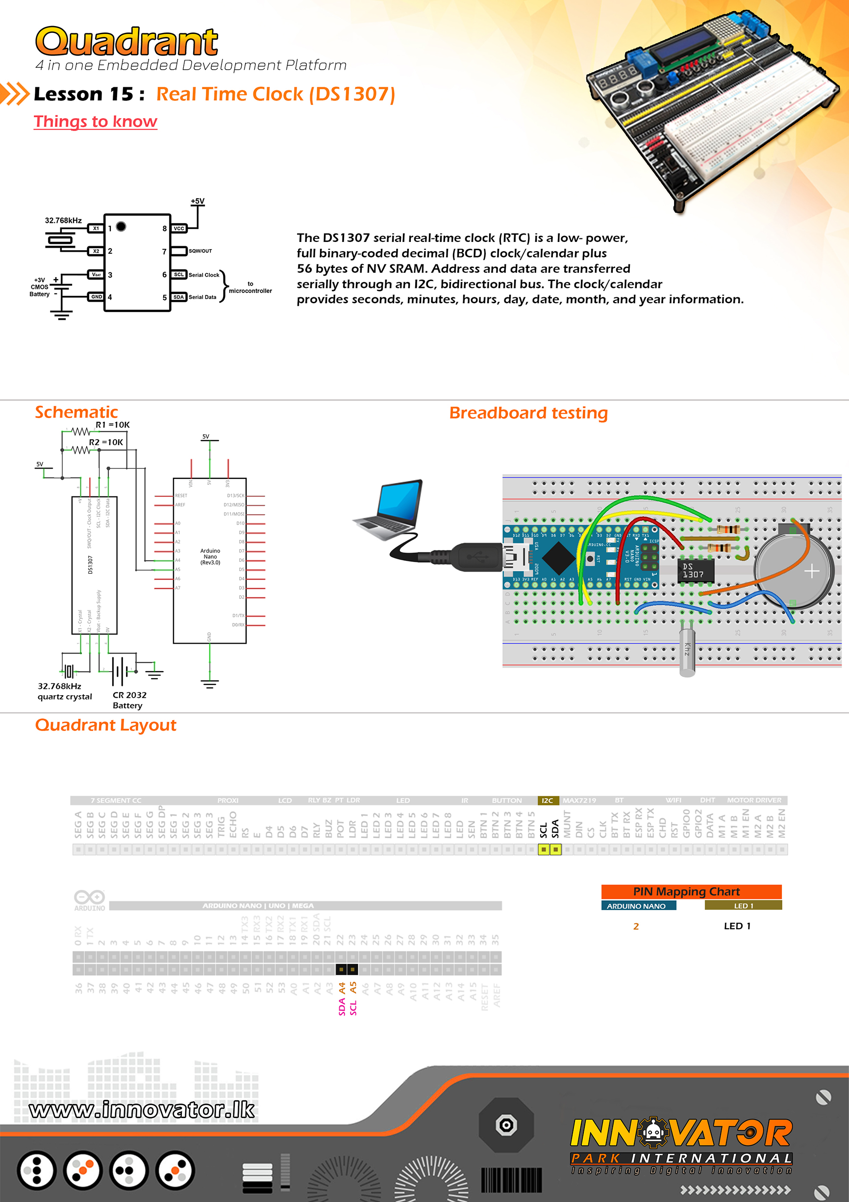
RTC Example.
------------------------------------------------------------------
Hardware setup :
Connect Arduino analog PIN 4(A4) to I2C SDA PIN
Connect Arduino analog PIN 5(A5) TO I2C SCL PIN
------------------------------------------------------------------
I2C device at address 0x27 = 16*2 LCD
I2C device at address 0x50 = EEPROM
I2C device at address 0x68 = 1307 RTC
------------------------------------------------------------------
22 march 2021
*/
#include "Wire.h"//including wire library in order to communicate with i2c bus devices.
#include "RTClib.h"//including real time clock library in order to use its functions.
RTC_DS1307 rtc;//creating a rtc object.
char daysOfTheWeek[7][12] = {"Sunday", "Monday", "Tuesday", "Wednesday", "Thursday", "Friday", "Saturday"};//char array for storing the days of a week.
void setup () {
Serial.begin(9600);//starting serial communication between arduino and computer.
if (! rtc.begin()) {//check if we can connect to the rtc module.
Serial.println("Couldn't find RTC");//if we can't connect to rtc module, print a message to serial monitor.
while (1);//keep checking until we are able to connect to the rtc module.
}
if (! rtc.isrunning()) {//check if rtc is running.
Serial.println("RTC is NOT running!");//else print message to the serial monitor.
rtc.adjust(DateTime(2021, 3, 22, 10, 00, 0));//adjusting date and time.
}
}
void loop () {
DateTime now = rtc.now(); //obtaining current the date and time.
//printing all information to serial monitor.
Serial.print(now.year(), DEC);
Serial.print('/');
Serial.print(now.month(), DEC);
Serial.print('/');
Serial.print(now.day(), DEC);
Serial.print(" (");
Serial.print(daysOfTheWeek[now.dayOfTheWeek()]);//obtaining the day of the week from the "daysOfTheWeek" array.
Serial.print(") ");
Serial.print(now.hour(), DEC);
Serial.print(':');
Serial.print(now.minute(), DEC);
Serial.print(':');
Serial.print(now.second(), DEC);
Serial.println();
delay(3000);//keep a 3 second time delay between each serial print.
}
/*
INNOVATOR INTERNATIONAL (PVT)LTD.
https://www.innovator.lk/
--------------------------------------------------------
Development Platform : Quadrant 1.0
(embedded development platform)
--------------------------------------------------------
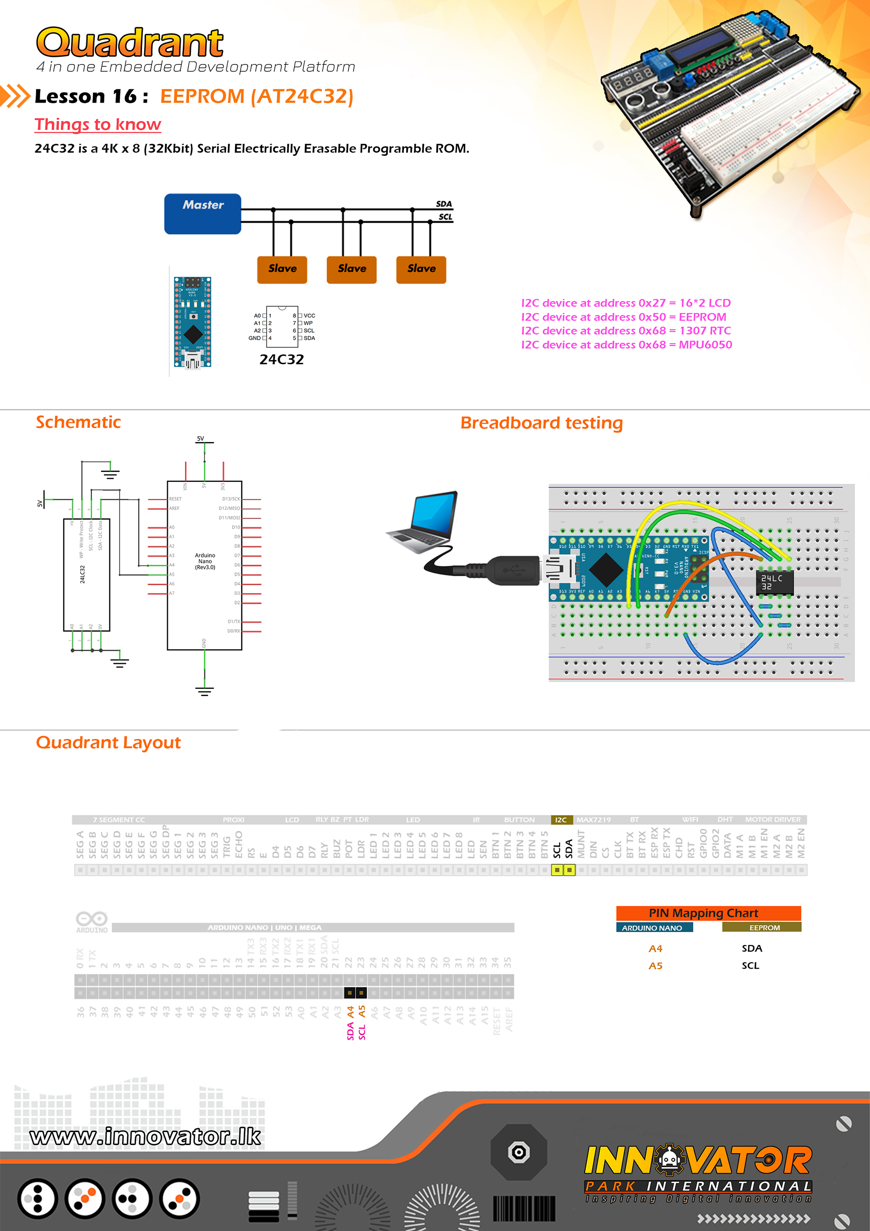
EEPROM Example.
--------------------------------------------------------
Hardware setup :
Connect Arduino analog PIN 4(A4) to I2C SDA PIN
Connect Arduino analog PIN 5(A5) TO I2C SCL PIN
--------------------------------------------------------
I2C device at address 0x27 = 16*2 LCD
I2C device at address 0x50 = EEPROM
I2C device at address 0x68 = 1307 RTC
I2C device at address 0x68 = MPU6050
--------------------------------------------------------
24 march 2021
*/
#include "Wire.h" //including wire library, in oder to communicate with i2c bus devices.
int EEPROM_I2C_ADDRESS = 0x50;//address of the AT24c32 eeprom chip on i2c bus.
void setup()
{
Wire.begin();//initializing connection to the i2c devices.
Serial.begin(9600);//starting serial communication between arduino and computer.
int address = 0; // starting address in the eeprom.
byte val = 100; // value to write to the eeprom.
writeAddress(address, val);//writing data to eeprom.
byte readVal = readAddress(address);//variable to hold the vale read from eeprom.
Serial.print("The returned value is ");//printing a message to serial monitor.
Serial.println(readVal);//printing the value to serial monitor.
}
void loop()
{
}
void writeAddress(int address, byte val)//function to write data to eeprom.
{
Wire.beginTransmission(EEPROM_I2C_ADDRESS); //starting data transmission with the device at specified address.
Wire.write((int)(address >> 8)); // MSB most significant bit.
Wire.write((int)(address & 0xFF)); // LSB least significant bit.
Wire.write(val);//writing data to wire.
Wire.endTransmission();//closing transmition.
delay(5);//wait for 5 microseconds.
}
byte readAddress(int address)//function to read data from eeprom.
{
byte rData = 0xFF; // variable to hold the data read from eeprom.
Wire.beginTransmission(EEPROM_I2C_ADDRESS);//starting data transmission with the device at specified address.
Wire.write((int)(address >> 8)); // writing data to (MSB) most significant bit.
Wire.write((int)(address & 0xFF)); // writing data to (LSB) least significant bit.
Wire.endTransmission();//closing transmission.
Wire.requestFrom(EEPROM_I2C_ADDRESS, 1); // reqesting data.
rData = Wire.read(); // reading data from eeprom and storing data un the variable.
return rData;//returning stored value.
}
/*
  INNOVATOR INTERNATIONAL (PVT)LTD.
  https://www.innovator.lk/
  --------------------------------------------------------
  Development Platform : Quadrant 1.0
  (embedded development platform)
  --------------------------------------------------------
   Hardware setup :
   connect A4 PIN to SDA
   connect A5 PIN to SCL
  ---------------------------------------------------------------
  I2C device at address 0x27 = 16*2 LCD
  I2C device at address 0x50 = EEPROM
  I2C device at address 0x68 = 1307 RTC
  I2C device at address 0x68 = MPU6050
  --------------------------------------------------------
  24 march 2021
*/


#include "MPU6050_tockn.h" //including mpu6050's library.
#include "Wire.h"//including wire libraary to comunicate with i2c devices.

MPU6050 mpu6050(Wire);

long timer = 0;//variable for hoding the timer value.

void setup() {
  Serial.begin(9600);//starting serial communication between arduino and computer.
  Wire.begin();//starting i2c communication.
  mpu6050.begin();
  mpu6050.calcGyroOffsets(true);
}

void loop() {
  mpu6050.update();

  if (millis() - timer > 1000) {//one second non-blockin delay.

    //print all information to serial monitor.
    Serial.println("=======================================================");
    Serial.print("temp : "); Serial.println(mpu6050.getTemp());
    Serial.print("accX : "); Serial.print(mpu6050.getAccX());
    Serial.print("  accY : "); Serial.print(mpu6050.getAccY());
    Serial.print("  accZ : "); Serial.println(mpu6050.getAccZ());

    Serial.print("gyroX : "); Serial.print(mpu6050.getGyroX());
    Serial.print("  gyroY : "); Serial.print(mpu6050.getGyroY());
    Serial.print("  gyroZ : "); Serial.println(mpu6050.getGyroZ());

    Serial.print("accAngleX : "); Serial.print(mpu6050.getAccAngleX());
    Serial.print("  accAngleY : "); Serial.println(mpu6050.getAccAngleY());

    Serial.print("gyroAngleX : "); Serial.print(mpu6050.getGyroAngleX());
    Serial.print("  gyroAngleY : "); Serial.print(mpu6050.getGyroAngleY());
    Serial.print("  gyroAngleZ : "); Serial.println(mpu6050.getGyroAngleZ());

    Serial.print("angleX : "); Serial.print(mpu6050.getAngleX());
    Serial.print("  angleY : "); Serial.print(mpu6050.getAngleY());
    Serial.print("  angleZ : "); Serial.println(mpu6050.getAngleZ());
    Serial.println("=======================================================");
    timer = millis();

  }

}
/*
INNOVATOR INTERNATIONAL (PVT)LTD.
https://www.innovator.lk/
------------------------------------------------------------------------------------
Development Platform : Quadrant 1.0
(embedded development platform)
------------------------------------------------------------------------------------
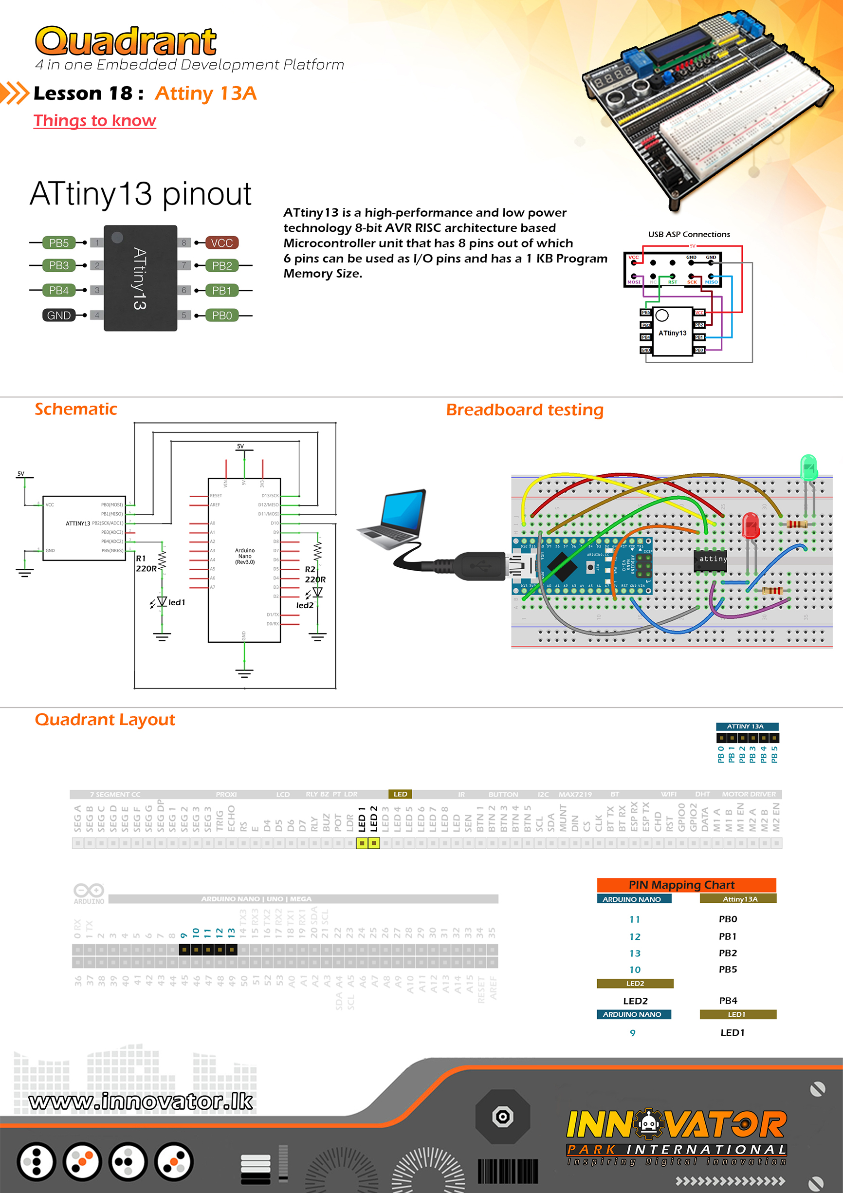
Attiny13 Example.
------------------------------------------------------------------------------------
Hardware setup :
Connect PB0 to Arduino digital PIN 11(D11)
Connect PB1 to Arduino digital PIN 12(D12)
Connect PB2 to Arduino digital PIN 13(D13)
Connect PB5 to Arduino digital PIN 10(D11)
Connect LED1 to Arduino digital PIN 9(D9)
Connect PB4 to LED2
------------------------------------------------------------------------------------
install : https://mcudude.github.io/MicroCore/package_MCUdude_MicroCore_index.json
to Arduino IDE.
------------------------------------------------------------------------------------
then go to File -> ArduinoISP -> upload the sketch to Arduino board.
if ArduinoISP is working you'll see LED1 fade in and fade off.
------------------------------------------------------------------------------------
now select tools -> board -> microcore -> Attiny13.
then go to tools -> and select Arduino as ISP.
now tools -> burn bootloader.
------------------------------------------------------------------------------------
now go to file -> examples -> basic -> blink.
change "LED_BUILTIN" to "4"
then go to sketch -> upload using programmer.
if everything is gone accordingly you'll see LED2 blinking.
------------------------------------------------------------------------------------
24 march 2021
*/
void setup() {
pinMode(4, OUTPUT);
}
void loop() {
digitalWrite(4, HIGH);
delay(1000);
digitalWrite(LED_BUILTIN, LOW);
delay(1000);
}
/*
INNOVATOR INTERNATIONAL (PVT)LTD.
https://www.innovator.lk/
--------------------------------------------------------
Development Platform : Quadrant 1.0
(embedded development platform)
--------------------------------------------------------
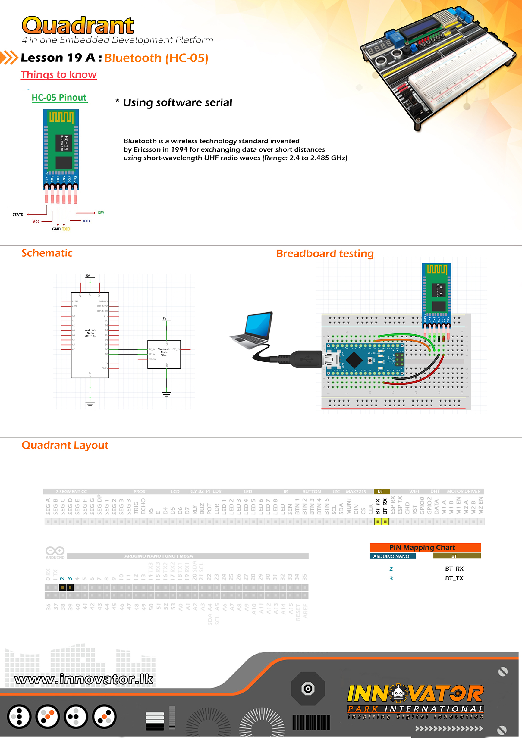
Bluetooth receive Example.
--------------------------------------------------------
Hardware setup :
Connect BT RX PIN to Arduino Digital PIN-> 2(D2)
Connect BT TX PIN to Arduino Digital PIN-> 3(D3)
--------------------------------------------------------
24 march 2021
*/
#include "SoftwareSerial.h" //including the software serial library.
SoftwareSerial btm(3, 2); // rx tx // initiating software serial object.
char c;//variable to hold the character recived by the serial data.
void setup() {
btm.begin(9600);//starting software serial communication.
Serial.begin(9600);//starting serial communication between arduino and computer.
}
void loop() {
if (btm.available() > 0) {//check if software serial is containing any data.
while (btm.available() > 0) {//while there is data,
c = btm.read();//read it and store it in the variable called "c".
Serial.print(c);//printing stored variable to the serial monitor.
}
}
}
/*
INNOVATOR INTERNATIONAL (PVT)LTD.
https://www.innovator.lk/
--------------------------------------------------------
Development Platform : Quadrant 1.0
(embedded development platform)
--------------------------------------------------------
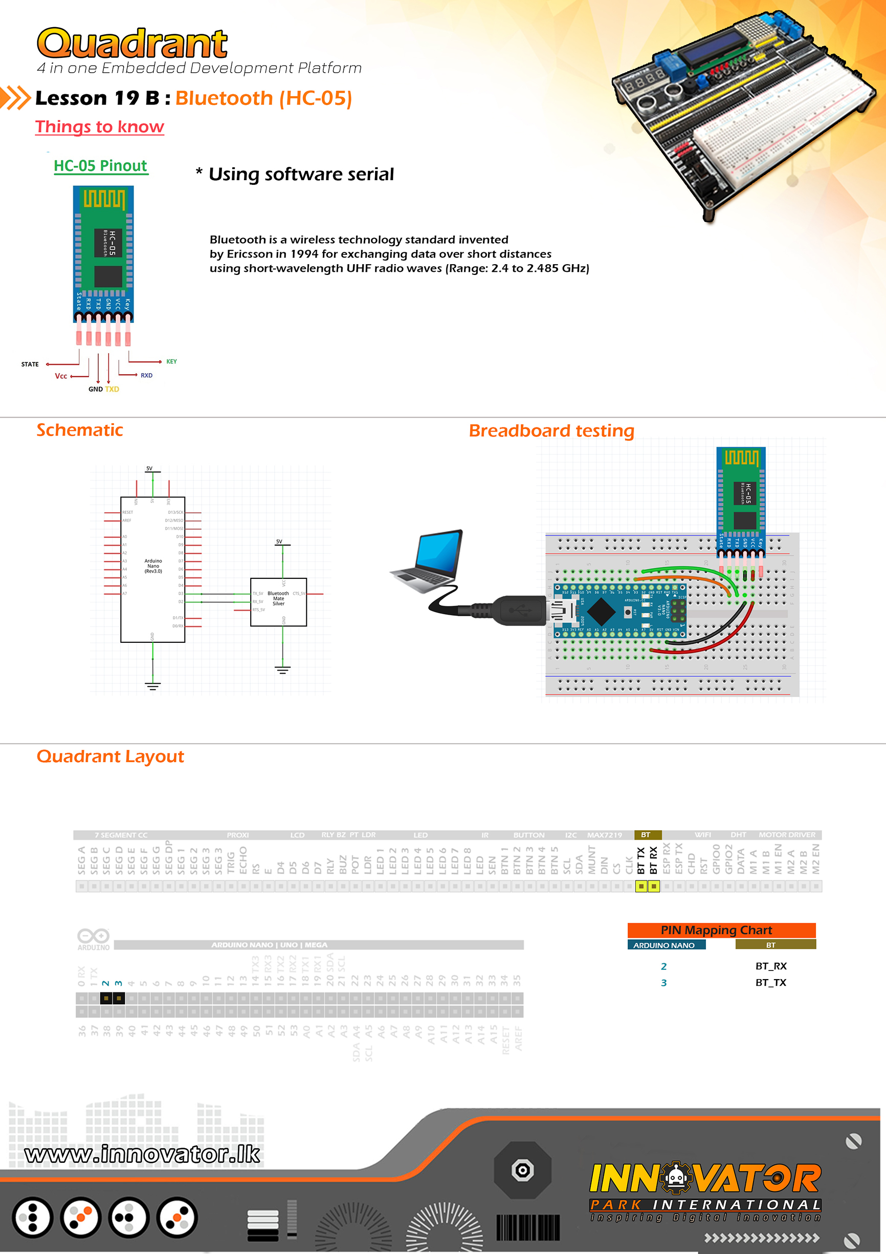
Bluetooth Send Example.
--------------------------------------------------------
Hardware setup :
connect BT RX PIN to Arduino Digital PIN-> 2(D2)
connect BT TX PIN to Arduino Digital PIN-> 3(D3)
--------------------------------------------------------
24 march 2021
*/
#include "SoftwareSerial.h"//including the software serial library.
SoftwareSerial btm(3, 2);// initiating software serial object.
void setup() {
btm.begin(9600);//starting software serial communication.
}
void loop() {
btm.println("this is from Quadrant :) ");//printing a message to software serial.
delay(1000);//keep a one second delay between each serial print.
}
/*
INNOVATOR INTERNATIONAL (PVT)LTD.
https://www.innovator.lk/
--------------------------------------------------------
Development Platform : Quadrant 1.0
(embedded development platform)
--------------------------------------------------------
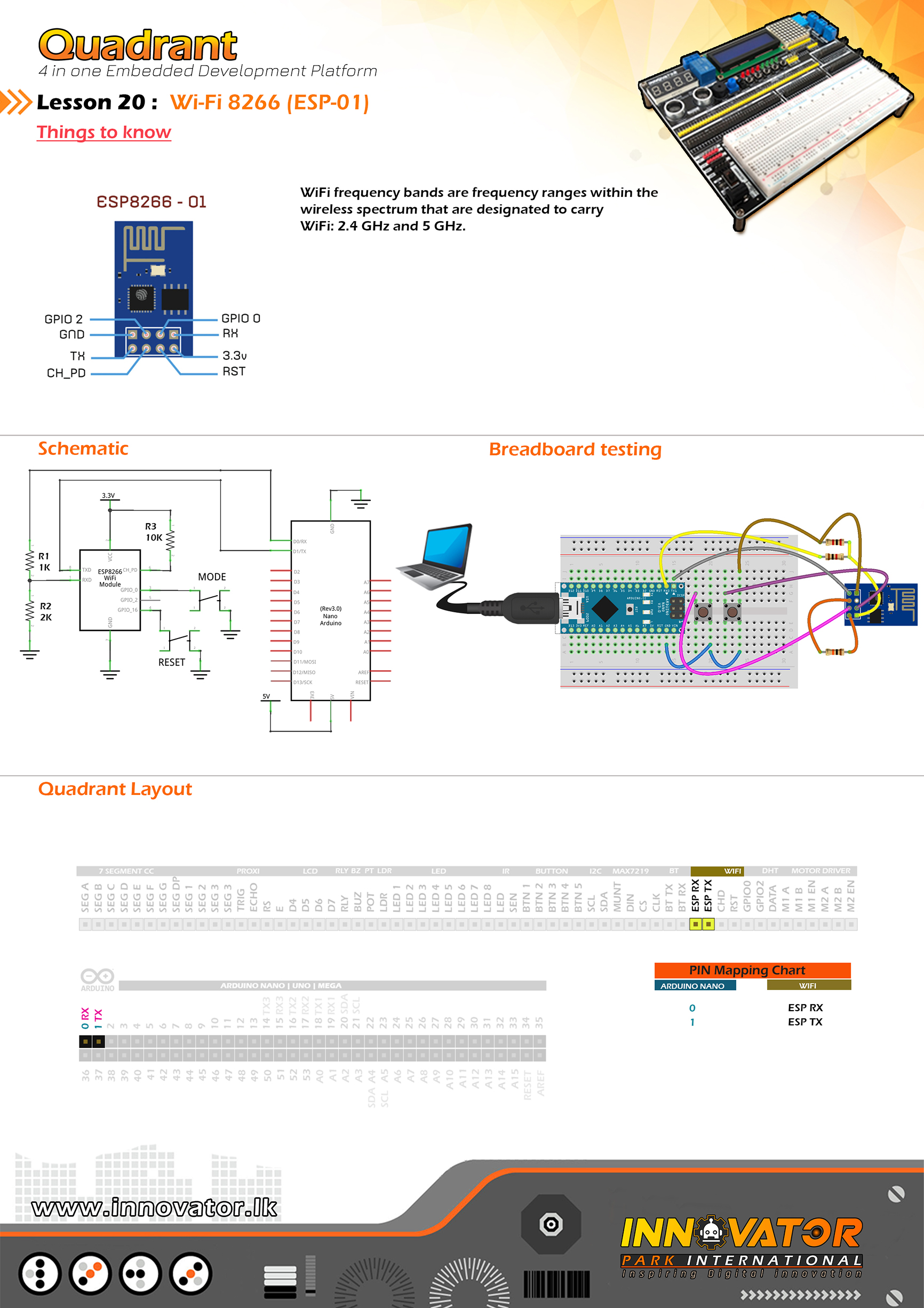
ESP01 WI-FI Example.
--------------------------------------------------------
Hardware setup :
Connect WIFI ESP RX of wifi to Arduino (0 PIN)RX.
Connect WIFI ESP TX of wifi to Arduino (1 PIN)TX.
Connect WIFI RST PIN to BTN 1 PIN.
Connect WIFI GPIO 0 PIN to BTN 2 PIN.
--------------------------------------------------------
press and hold GPIO0 and RST buttons together and
release the RST button first then GPIO0.
this will put the esp8266 to programing mode.
now press upload button in Arduino IDE.
--------------------------------------------------------
24 march 2021
*/
#include "ESP8266WiFi.h"
//controling a led through wifi.
// to program esp8266.
const char* ssid = "**********";//type your ssid.
const char* password = "**********";//type your password.
int ledPin = 2; // GPIO2 of ESP8266.
WiFiServer server(80);//creating a wifi servr object.
void setup() {
Serial.begin(9600);//starting serial communication between arduino and computer.
delay(10);//waiting to ten seconds to be elapsed.
pinMode(ledPin, OUTPUT);//initializing ledpin as output pin.
digitalWrite(ledPin, LOW);//turning off the led at startup.
// connect to WiFi network.
Serial.println();
Serial.println();
Serial.print("Connecting to ");
Serial.println(ssid);
WiFi.begin(ssid, password);
while (WiFi.status() != WL_CONNECTED) {
delay(500);
Serial.print(".");
}
Serial.println("");
Serial.println("WiFi connected");
// starting the server.
server.begin();
Serial.println("Server started");
// printing the IP address.
Serial.print("Use this URL in a web browser to connect: ");
Serial.print("http://");
Serial.print(WiFi.localIP());
Serial.println("/");
}
void loop() {
// check if a client has connected.
WiFiClient client = server.available();
if (!client) {
return;
}
// wait until the client sends some data.
Serial.println("new client");
while (!client.available()) {
delay(1);
}
// read the first line of the request.
String request = client.readStringUntil('r');
Serial.println(request);
client.flush();
// check html request.
// set ledPin according to the request
int value = LOW;
if (request.indexOf("/LED=ON") != -1) {
digitalWrite(ledPin, HIGH);
value = HIGH;
}
if (request.indexOf("/LED=OFF") != -1) {
digitalWrite(ledPin, LOW);
value = LOW;
}
// return the response
client.println("HTTP/1.1 200 OK");
client.println("Content-Type: text/html");
client.println(""); // do not forget this one
client.println("");
client.println("");
client.print("Led pin is now: ");
if (value == HIGH) {
client.print("On");
} else {
client.print("Off");
}
client.println("");
client.println("Click here turn the LED on pin 2 ON");
client.println("Click here turn the LED on pin 2 OFF");
client.println("");
delay(1);
Serial.println("Client disonnected");
Serial.println("");
}/*
INNOVATOR INTERNATIONAL (PVT)LTD.
https://www.innovator.lk/
------------------------------------------------------------
Development Platform : Quadrant 1.0
(embedded development platform)
------------------------------------------------------------
SSD DICE.
------------------------------------------------------------
Hardware setup :
Connect "7 Segment[cc]" PINs near dotmatrix to the PINs
of "7 Segment[cc]" beleow the 4digit seven segment display.
Connect MAX7219 DOUT PIN to Arduino digital PIN 2(D2).
Connect MAX7219 CS PIN to Arduino digital PIN 3(D3).
Connect MAX7219 CLK PIN to Arduino digital PIN 4(D4).
connect Arduino analog PIN 4(A4) to SDA
connect Arduino analog PIN 4(A5) to SCL
------------------------------------------------------------
5 may 2021
*/
#include "LedControl.h"
#include "LiquidCrystal_I2C.h"
int DIN = 2;
int CLK = 3;
int CS = 4;
LedControl lc = LedControl(DIN, CLK, CS, 1);
LiquidCrystal_I2C lcd(0x27, 16, 2);
int START_BUTTON = A1;
int STOP_BUTTON = A2;
boolean RUN = false;
int RANDOM_NUMBER = 0;
unsigned long previousMillis = 0;
const long interval = 70;
int T = 0;
void setup() {
lcd.begin();
lcd.backlight();
lcd.setCursor(0, 0);
lcd.print(" SSD Dice");
delay(1000);
lc.shutdown(0, false);
lc.setIntensity(0, 15);
lc.clearDisplay(0);
lc.setDigit(0, 3, 0, true);
lc.setDigit(0, 2, 0, true);
lc.setDigit(0, 1, 0, true);
lc.setDigit(0, 0, 0, true);
}
void loop() {
if (!digitalRead(START_BUTTON)) {
RUN = true;
delay(100);
}
if (!digitalRead(STOP_BUTTON)) {
RUN = false;
T = 0;
RANDOM_NUMBER = random(1, 7);
lc.setDigit(0, 0, 0, true);
lc.setDigit(0, 1, 0, true);
lc.setDigit(0, 2, 0, true);
lc.setDigit(0, 3, RANDOM_NUMBER, true);
lcd.clear();
lcd.setCursor(0, 0);
lcd.print(" SSD Dice");
}
if (RUN) {
for (int i = 0; i < 10; i++) { lc.setDigit(0, 0, i, false); lc.setDigit(0, 1, i, false); lc.setDigit(0, 2, i, false); lc.setDigit(0, 3, i, false); delay(10); } lcdu(); } } void lcdu() { unsigned long currentMillis = millis(); if (currentMillis - previousMillis >= interval) {
T++;
previousMillis = currentMillis;
}
lcd.setCursor(0, 1);
lcd.print("Rolling");
if (T == 1) {
lcd.setCursor(7, 1);
lcd.print(".");
}
if (T == 2) {
lcd.setCursor(8, 1);
lcd.print(".");
}
if (T == 3) {
lcd.setCursor(9, 1);
lcd.print(".");
}
if (T == 4) {
lcd.setCursor(10, 1);
lcd.print(".");
T = 0;
lcd.clear();
lcd.setCursor(0, 0);
lcd.print(" SSD Dice");
}
}/*
INNOVATOR INTERNATIONAL (PVT)LTD.
https://www.innovator.lk/
------------------------------------------------------------
Development Platform : Quadrant 1.0
(embedded development platform)
------------------------------------------------------------
SSD COUNTER.
------------------------------------------------------------
Hardware setup :
Connect "7 Segment[cc]" PINs near dotmatrix to the PINs
of "7 Segment[cc]" beleow the 4digit seven segment display.
Connect MAX7219 DOUT PIN to Arduino digital PIN 2(D2).
Connect MAX7219 CS PIN to Arduino digital PIN 3(D3).
Connect MAX7219 CLK PIN to Arduino digital PIN 4(D4).
connect Arduino analog PIN 4(A4) to SDA
connect Arduino analog PIN 4(A5) to SCL
------------------------------------------------------------
5 may 2021
*/
#include "LedControl.h"
#include "LiquidCrystal_I2C.h"
int DIN = 2;
int CLK = 3;
int CS = 4;
LedControl lc = LedControl(DIN, CLK, CS, 1);
LiquidCrystal_I2C lcd(0x27, 16, 2);
int MAX = 9999;
void setup() {
lcd.begin();
lcd.backlight();
lcd.setCursor(0, 0);
lcd.print(" SSD Counter");
delay(1000);
lc.shutdown(0, false);
lc.setIntensity(0, 15);
lc.clearDisplay(0);
lc.setDigit(0, 3, 1, false);
lc.setDigit(0, 2, 2, true);
lc.setDigit(0, 1, 3, true);
lc.setDigit(0, 0, 4, false);
}
void loop() {
for (int i = 0; i < MAX; i++) {
lc.setDigit(0, 3, i % 10, false);
lc.setDigit(0, 2, (i / 10 ) % 10, false);
lc.setDigit(0, 1, (i / 100 ) % 10, false);
lc.setDigit(0, 0, (i / 1000 ) % 10, false);
delay(500);
}
}/*
INNOVATOR INTERNATIONAL (PVT)LTD.
https://www.innovator.lk/
------------------------------------------------------------
Development Platform : Quadrant 1.0
(embedded development platform)
------------------------------------------------------------
MPU6050 WITH LCD .
------------------------------------------------------------
Hardware setup :
connect Arduino analog PIN 4(A4) to SDA
connect Arduino analog PIN 4(A5) to SCL
------------------------------------------------------------
I2C device at address 0x27 = 16*2 LCD
I2C device at address 0x50 = EEPROM
I2C device at address 0x68 = 1307 RTC
I2C device at address 0x68 = MPU6050
------------------------------------------------------------
7 may 2021
*/
#include "Wire.h"
#include "LiquidCrystal_I2C.h"
LiquidCrystal_I2C lcd(0x27, 16, 2);
int DIN = 2;
int CS = 4;
int CLK = 3;
int acc_x, acc_y, acc_z;
int gyro_x, gyro_y, gyro_z;
float temp;
long loop_timer;
boolean ACC = true;
int BUTTON = A1;
int A = 0;
int G = 0;
void setup() {
Wire.begin();
lcd.begin();
setup_mpu_6050_registers();
Serial.begin(9600);
lcd.clear();
lcd.setCursor(0, 0);
lcd.print(" MPU 6050");
delay(1000);
pinMode(BUTTON, INPUT);
}
void loop() {
if (!digitalRead(BUTTON)) {
if (ACC == false) {
ACC = true;
} else {
ACC = false;
}
}
read_mpu_6050_data();
if (ACC) {
G = 0;
if (A == 0) {
lcd.clear();
lcd.setCursor(0, 0);
lcd.print("Accelerometer");
A++;
delay(1000);
}
Serial.println("--------------------------");
Serial.print("Accelerometer X Axis :" );
Serial.println(acc_x);
Serial.print("Accelerometer Y Axis : ");
Serial.println(acc_y);
Serial.print("Accelerometer Z Axis : ");
Serial.println(acc_z);
Serial.print("Temperature C : ");
Serial.println(temp / 340.00 + 36.53);
Serial.println("--------------------------");
lcd.clear();
lcd.setCursor(0, 0);
lcd.print("X:");
lcd.setCursor(2, 0);
lcd.print(acc_x);
lcd.setCursor(9, 0);
lcd.print("Y:");
lcd.setCursor(11, 0);
lcd.print(acc_y);
lcd.setCursor(0, 1);
lcd.print("Z:");
lcd.setCursor(2, 1);
lcd.print(acc_z);
lcd.setCursor(8, 1);
lcd.print("T:");
lcd.setCursor(10, 1);
lcd.print(temp / 340.00 + 36.53);
lcd.setCursor(15, 1);
lcd.print("C");
delay(1000);
} else {
A = 0;
if (G == 0) {
lcd.clear();
lcd.setCursor(0, 0);
lcd.print("Gyroscope");
G++;
delay(1000);
}
Serial.println("--------------------------");
Serial.print("Gyroscope X Axis :" );
Serial.println(gyro_x);
Serial.print("Gyroscope Y Axis : ");
Serial.println(gyro_y);
Serial.print("Gyroscope Z Axis : ");
Serial.println(gyro_z);
Serial.print("Temperature C : ");
Serial.println(temp / 340.00 + 36.53);
Serial.println("--------------------------");
lcd.clear();
lcd.setCursor(0, 0);
lcd.print("X:");
lcd.setCursor(2, 0);
lcd.print(gyro_x);
lcd.setCursor(9, 0);
lcd.print("Y:");
lcd.setCursor(11, 0);
lcd.print(gyro_y);
lcd.setCursor(0, 1);
lcd.print("Z:");
lcd.setCursor(2, 1);
lcd.print(gyro_z);
lcd.setCursor(8, 1);
lcd.print("T:");
lcd.setCursor(10, 1);
lcd.print(temp / 340.00 + 36.53);
lcd.setCursor(15, 1);
lcd.print("C");
delay(1000);
}
}
void setup_mpu_6050_registers() {
Wire.beginTransmission(0x69);
Wire.write(0x6B);
Wire.write(0x00);
Wire.endTransmission();
Wire.beginTransmission(0x69);
Wire.write(0x1C);
Wire.write(0x10);
Wire.endTransmission();
Wire.beginTransmission(0x69);
Wire.write(0x1B);
Wire.write(0x08);
Wire.endTransmission();
}
void read_mpu_6050_data() {
Wire.beginTransmission(0x69);
Wire.write(0x3B);
Wire.endTransmission();
Wire.requestFrom(0x69, 14);
while (Wire.available() < 14);
acc_x = Wire.read() << 8 | Wire.read();
acc_y = Wire.read() << 8 | Wire.read();
acc_z = Wire.read() << 8 | Wire.read();
temp = Wire.read() << 8 | Wire.read();
gyro_x = Wire.read() << 8 | Wire.read();
gyro_y = Wire.read() << 8 | Wire.read();
gyro_z = Wire.read() << 8 | Wire.read();
}/*
INNOVATOR INTERNATIONAL (PVT)LTD.
https://www.innovator.lk/
------------------------------------------------------------
Development Platform : Quadrant 1.0
(embedded development platform)
------------------------------------------------------------
SSD DICE WITH ANIMATION.
------------------------------------------------------------
Hardware setup :
Connect "7 Segment[cc]" PINs near dotmatrix to the PINs
of "7 Segment[cc]" beleow the 4digit seven segment display.
Connect MAX7219 DOUT PIN to Arduino digital PIN 2(D2).
Connect MAX7219 CS PIN to Arduino digital PIN 3(D3).
Connect MAX7219 CLK PIN to Arduino digital PIN 4(D4).
connect Arduino analog PIN 4(A4) to SDA
connect Arduino analog PIN 4(A5) to SCL
------------------------------------------------------------
7 may 2021
*/
#include "LedControl.h"
#include "LiquidCrystal_I2C.h"
int DIN = 2;
int CLK = 3;
int CS = 4;
LedControl lc = LedControl(DIN, CLK, CS, 1);
LiquidCrystal_I2C lcd(0x27, 16, 2);
int START_BUTTON = A1;
int STOP_BUTTON = A2;
boolean RUN = false;
int RANDOM_NUMBER = 0;
unsigned long previousMillis = 0;
const long interval = 100;
int T = 0;
void setup() {
lcd.begin();
lcd.backlight();
lcd.setCursor(0, 0);
lcd.print(" SSD Dice");
delay(1000);
lc.shutdown(0, false);
lc.setIntensity(0, 15);
lc.clearDisplay(0);
lc.setDigit(0, 3, 0, true);
lc.setDigit(0, 2, 0, true);
lc.setDigit(0, 1, 0, true);
lc.setDigit(0, 0, 0, true);
}
void loop() {
if (!digitalRead(START_BUTTON)) {
RUN = true;
delay(100);
}
if (!digitalRead(STOP_BUTTON)) {
RUN = false;
T = 0;
RANDOM_NUMBER = random(1, 7);
lc.setDigit(0, 0, 0, true);
lc.setDigit(0, 1, 0, true);
lc.setDigit(0, 2, 0, true);
lc.setDigit(0, 3, RANDOM_NUMBER, true);
}
if (RUN) {
ssdu();
}
}
void ssdu() {
int i = 0;
unsigned long currentMillis = millis();
if (currentMillis - previousMillis >= interval) {
T++;
lc.setDigit(0, 0, random(1, 9), false);
lc.setDigit(0, 1, random(1, 9), false);
lc.setDigit(0, 2, random(1, 9), false);
lc.setDigit(0, 3, random(1, 9), false);
previousMillis = currentMillis;
}
if (T == 1) {
lc.setDigit(0, 0, i, true);
}
if (T == 2) {
lc.setDigit(0, 1, i, true);
}
if (T == 3) {
lc.setDigit(0, 2, i, true);
}
if (T == 4) {
lc.setDigit(0, 3, i, true);
T = 0;
}
}/*
INNOVATOR INTERNATIONAL (PVT)LTD.
https://www.innovator.lk/
------------------------------------------------------------
Development Platform : Quadrant 1.0
(embedded development platform)
------------------------------------------------------------
Buzzer Melodies.
------------------------------------------------------------
Hardware setup :
Connect BUZZER PIN to Arduino digital PIN 11(D11).
connect Arduino analog PIN 4(A4) to SDA
connect Arduino analog PIN 4(A5) to SCL
------------------------------------------------------------
7 may 2021
*/
#include "LiquidCrystal_I2C.h"
//--------------------------------------------------------------------------------
int buzzer = 11;
//--------------------------------------------------------------------------------
LiquidCrystal_I2C lcd(0x27, 16, 2);
//--------------------------------------------------------------------------------
#define NOTE_B0 31
#define NOTE_C1 33
#define NOTE_CS1 35
#define NOTE_D1 37
#define NOTE_DS1 39
#define NOTE_E1 41
#define NOTE_F1 44
#define NOTE_FS1 46
#define NOTE_G1 49
#define NOTE_GS1 52
#define NOTE_A1 55
#define NOTE_AS1 58
#define NOTE_B1 62
#define NOTE_C2 65
#define NOTE_CS2 69
#define NOTE_D2 73
#define NOTE_DS2 78
#define NOTE_E2 82
#define NOTE_F2 87
#define NOTE_FS2 93
#define NOTE_G2 98
#define NOTE_GS2 104
#define NOTE_A2 110
#define NOTE_AS2 117
#define NOTE_B2 123
#define NOTE_C3 131
#define NOTE_CS3 139
#define NOTE_D3 147
#define NOTE_DS3 156
#define NOTE_E3 165
#define NOTE_F3 175
#define NOTE_FS3 185
#define NOTE_G3 196
#define NOTE_GS3 208
#define NOTE_A3 220
#define NOTE_AS3 233
#define NOTE_B3 247
#define NOTE_C4 262
#define NOTE_CS4 277
#define NOTE_D4 294
#define NOTE_DS4 311
#define NOTE_E4 330
#define NOTE_F4 349
#define NOTE_FS4 370
#define NOTE_G4 392
#define NOTE_GS4 415
#define NOTE_A4 440
#define NOTE_AS4 466
#define NOTE_B4 494
#define NOTE_C5 523
#define NOTE_CS5 554
#define NOTE_D5 587
#define NOTE_DS5 622
#define NOTE_E5 659
#define NOTE_F5 698
#define NOTE_FS5 740
#define NOTE_G5 784
#define NOTE_GS5 831
#define NOTE_A5 880
#define NOTE_AS5 932
#define NOTE_B5 988
#define NOTE_C6 1047
#define NOTE_CS6 1109
#define NOTE_D6 1175
#define NOTE_DS6 1245
#define NOTE_E6 1319
#define NOTE_F6 1397
#define NOTE_FS6 1480
#define NOTE_G6 1568
#define NOTE_GS6 1661
#define NOTE_A6 1760
#define NOTE_AS6 1865
#define NOTE_B6 1976
#define NOTE_C7 2093
#define NOTE_CS7 2217
#define NOTE_D7 2349
#define NOTE_DS7 2489
#define NOTE_E7 2637
#define NOTE_F7 2794
#define NOTE_FS7 2960
#define NOTE_G7 3136
#define NOTE_GS7 3322
#define NOTE_A7 3520
#define NOTE_AS7 3729
#define NOTE_B7 3951
#define NOTE_C8 4186
#define NOTE_CS8 4435
#define NOTE_D8 4699
#define NOTE_DS8 4978
#define REST 0
int tempo = 85;
int melody_GAME_OF_THRONES[] = {
NOTE_G4, 8, NOTE_C4, 8, NOTE_DS4, 16, NOTE_F4, 16, NOTE_G4, 8, NOTE_C4, 8, NOTE_DS4, 16, NOTE_F4, 16, //1
NOTE_G4, 8, NOTE_C4, 8, NOTE_DS4, 16, NOTE_F4, 16, NOTE_G4, 8, NOTE_C4, 8, NOTE_DS4, 16, NOTE_F4, 16,
NOTE_G4, 8, NOTE_C4, 8, NOTE_E4, 16, NOTE_F4, 16, NOTE_G4, 8, NOTE_C4, 8, NOTE_E4, 16, NOTE_F4, 16,
NOTE_G4, 8, NOTE_C4, 8, NOTE_E4, 16, NOTE_F4, 16, NOTE_G4, 8, NOTE_C4, 8, NOTE_E4, 16, NOTE_F4, 16,
NOTE_G4, -4, NOTE_C4, -4, //5
NOTE_DS4, 16, NOTE_F4, 16, NOTE_G4, 4, NOTE_C4, 4, NOTE_DS4, 16, NOTE_F4, 16, //6
NOTE_D4, -1, //7 and 8
NOTE_F4, -4, NOTE_AS3, -4,
NOTE_DS4, 16, NOTE_D4, 16, NOTE_F4, 4, NOTE_AS3, -4,
NOTE_DS4, 16, NOTE_D4, 16, NOTE_C4, -1,
NOTE_G4, -4, NOTE_C4, -4,
NOTE_DS4, 16, NOTE_F4, 16, NOTE_G4, 4, NOTE_C4, 4, NOTE_DS4, 16, NOTE_F4, 16, //6
NOTE_D4, -1,
NOTE_F4, -4, NOTE_AS3, -4,
NOTE_DS4, 16, NOTE_D4, 16, NOTE_F4, 4, NOTE_AS3, -4,
NOTE_DS4, 16, NOTE_D4, 16, NOTE_C4, -1, //11 and 12
NOTE_G4, -4, NOTE_C4, -4,
NOTE_DS4, 16, NOTE_F4, 16, NOTE_G4, 4, NOTE_C4, 4, NOTE_DS4, 16, NOTE_F4, 16,
NOTE_D4, -2,
NOTE_F4, -4, NOTE_AS3, -4,
NOTE_D4, -8, NOTE_DS4, -8, NOTE_D4, -8, NOTE_AS3, -8,
NOTE_C4, -1,
NOTE_C5, -2,
NOTE_AS4, -2,
NOTE_C4, -2,
NOTE_G4, -2,
NOTE_DS4, -2,
NOTE_DS4, -4, NOTE_F4, -4,
NOTE_G4, -1,
NOTE_C5, -2,
NOTE_AS4, -2,
NOTE_C4, -2,
NOTE_G4, -2,
NOTE_DS4, -2,
NOTE_DS4, -4, NOTE_D4, -4,
NOTE_C5, 8, NOTE_G4, 8, NOTE_GS4, 16, NOTE_AS4, 16, NOTE_C5, 8, NOTE_G4, 8, NOTE_GS4, 16, NOTE_AS4, 16,
NOTE_C5, 8, NOTE_G4, 8, NOTE_GS4, 16, NOTE_AS4, 16, NOTE_C5, 8, NOTE_G4, 8, NOTE_GS4, 16, NOTE_AS4, 16,
REST, 4, NOTE_GS5, 16, NOTE_AS5, 16, NOTE_C6, 8, NOTE_G5, 8, NOTE_GS5, 16, NOTE_AS5, 16,
NOTE_C6, 8, NOTE_G5, 16, NOTE_GS5, 16, NOTE_AS5, 16, NOTE_C6, 8, NOTE_G5, 8, NOTE_GS5, 16, NOTE_AS5, 16,
};
int notes = sizeof(melody_GAME_OF_THRONES) / sizeof(melody_GAME_OF_THRONES[0]) / 2;
int wholenote = (60000 * 4) / tempo;
int divider = 0, noteDuration = 0;
//--------------------------------------------------------------------------------
const float songSpeed = 1.0;
#define NOTE_C4 262
#define NOTE_D4 294
#define NOTE_E4 330
#define NOTE_F4 349
#define NOTE_G4 392
#define NOTE_A4 440
#define NOTE_B4 494
#define NOTE_C5 523
#define NOTE_D5 587
#define NOTE_E5 659
#define NOTE_F5 698
#define NOTE_G5 784
#define NOTE_A5 880
#define NOTE_B5 988
int notes_POI[] = {
NOTE_E4, NOTE_G4, NOTE_A4, NOTE_A4, 0,
NOTE_A4, NOTE_B4, NOTE_C5, NOTE_C5, 0,
NOTE_C5, NOTE_D5, NOTE_B4, NOTE_B4, 0,
NOTE_A4, NOTE_G4, NOTE_A4, 0,
NOTE_E4, NOTE_G4, NOTE_A4, NOTE_A4, 0,
NOTE_A4, NOTE_B4, NOTE_C5, NOTE_C5, 0,
NOTE_C5, NOTE_D5, NOTE_B4, NOTE_B4, 0,
NOTE_A4, NOTE_G4, NOTE_A4, 0,
NOTE_E4, NOTE_G4, NOTE_A4, NOTE_A4, 0,
NOTE_A4, NOTE_C5, NOTE_D5, NOTE_D5, 0,
NOTE_D5, NOTE_E5, NOTE_F5, NOTE_F5, 0,
NOTE_E5, NOTE_D5, NOTE_E5, NOTE_A4, 0,
NOTE_A4, NOTE_B4, NOTE_C5, NOTE_C5, 0,
NOTE_D5, NOTE_E5, NOTE_A4, 0,
NOTE_A4, NOTE_C5, NOTE_B4, NOTE_B4, 0,
NOTE_C5, NOTE_A4, NOTE_B4, 0,
NOTE_A4, NOTE_A4,
NOTE_A4, NOTE_B4, NOTE_C5, NOTE_C5, 0,
NOTE_C5, NOTE_D5, NOTE_B4, NOTE_B4, 0,
NOTE_A4, NOTE_G4, NOTE_A4, 0,
NOTE_E4, NOTE_G4, NOTE_A4, NOTE_A4, 0,
NOTE_A4, NOTE_B4, NOTE_C5, NOTE_C5, 0,
NOTE_C5, NOTE_D5, NOTE_B4, NOTE_B4, 0,
NOTE_A4, NOTE_G4, NOTE_A4, 0,
NOTE_E4, NOTE_G4, NOTE_A4, NOTE_A4, 0,
NOTE_A4, NOTE_C5, NOTE_D5, NOTE_D5, 0,
NOTE_D5, NOTE_E5, NOTE_F5, NOTE_F5, 0,
NOTE_E5, NOTE_D5, NOTE_E5, NOTE_A4, 0,
NOTE_A4, NOTE_B4, NOTE_C5, NOTE_C5, 0,
NOTE_D5, NOTE_E5, NOTE_A4, 0,
NOTE_A4, NOTE_C5, NOTE_B4, NOTE_B4, 0,
NOTE_C5, NOTE_A4, NOTE_B4, 0,
//End of Repeat
NOTE_E5, 0, 0, NOTE_F5, 0, 0,
NOTE_E5, NOTE_E5, 0, NOTE_G5, 0, NOTE_E5, NOTE_D5, 0, 0,
NOTE_D5, 0, 0, NOTE_C5, 0, 0,
NOTE_B4, NOTE_C5, 0, NOTE_B4, 0, NOTE_A4,
NOTE_E5, 0, 0, NOTE_F5, 0, 0,
NOTE_E5, NOTE_E5, 0, NOTE_G5, 0, NOTE_E5, NOTE_D5, 0, 0,
NOTE_D5, 0, 0, NOTE_C5, 0, 0,
NOTE_B4, NOTE_C5, 0, NOTE_B4, 0, NOTE_A4
};
int durations_POI[] = {
125, 125, 250, 125, 125,
125, 125, 250, 125, 125,
125, 125, 250, 125, 125,
125, 125, 375, 125,
125, 125, 250, 125, 125,
125, 125, 250, 125, 125,
125, 125, 250, 125, 125,
125, 125, 375, 125,
125, 125, 250, 125, 125,
125, 125, 250, 125, 125,
125, 125, 250, 125, 125,
125, 125, 125, 250, 125,
125, 125, 250, 125, 125,
250, 125, 250, 125,
125, 125, 250, 125, 125,
125, 125, 375, 375,
250, 125,
125, 125, 250, 125, 125,
125, 125, 250, 125, 125,
125, 125, 375, 125,
125, 125, 250, 125, 125,
125, 125, 250, 125, 125,
125, 125, 250, 125, 125,
125, 125, 375, 125,
125, 125, 250, 125, 125,
125, 125, 250, 125, 125,
125, 125, 250, 125, 125,
125, 125, 125, 250, 125,
125, 125, 250, 125, 125,
250, 125, 250, 125,
125, 125, 250, 125, 125,
125, 125, 375, 375,
250, 125, 375, 250, 125, 375,
125, 125, 125, 125, 125, 125, 125, 125, 375,
250, 125, 375, 250, 125, 375,
125, 125, 125, 125, 125, 500,
250, 125, 375, 250, 125, 375,
125, 125, 125, 125, 125, 125, 125, 125, 375,
250, 125, 375, 250, 125, 375,
125, 125, 125, 125, 125, 500
};
//--------------------------------------------------------------------------------
void setup() {
lcd.begin();
lcd.setCursor(0, 0);
lcd.print("Buzzer Melodies");
delay(1000);
}
void loop() {
for (int i = 0; i < 1; i++) {
PIRATES_OF_THE_CARIBBEAN();
}
delay(100);
for (int i = 0; i < 1; i++) {
GAME_OF_THRONES();
}
delay(100);
}
void GAME_OF_THRONES() {
lcd.clear();
lcd.setCursor(0, 0);
lcd.print("game of thrones");
for (int thisNote = 0; thisNote < notes * 2; thisNote = thisNote + 2) { divider = melody_GAME_OF_THRONES[thisNote + 1]; if (divider > 0) {
noteDuration = (wholenote) / divider;
} else if (divider < 0) {
noteDuration = (wholenote) / abs(divider);
noteDuration *= 1.5;
}
tone(buzzer, melody_GAME_OF_THRONES[thisNote], noteDuration * 0.9);
delay(noteDuration);
noTone(buzzer);
}
}
void PIRATES_OF_THE_CARIBBEAN() {
lcd.clear();
lcd.setCursor(0, 0);
lcd.print("pirates of the");
lcd.setCursor(0, 1);
lcd.print("caribbean");
const int totalNotes = sizeof(notes_POI) / sizeof(int);
for (int i = 0; i < totalNotes; i++)
{
const int currentNote = notes_POI[i];
float wait = durations_POI[i] / songSpeed;
if (currentNote != 0)
{
tone(buzzer, notes_POI[i], wait);
}
else
{
noTone(buzzer);
}
delay(wait);
}
}/*
INNOVATOR INTERNATIONAL (PVT)LTD.
https://www.innovator.lk/
------------------------------------------------------------
Development Platform : Quadrant 1.0
(embedded development platform)
------------------------------------------------------------
MPU6050 LEVEL METER.
------------------------------------------------------------
Hardware setup :
connect LED3 PIN to Arduino digital PIN 8(D8).
connect LED4 PIN to Arduino digital PIN 9(D9).
connect LED5 PIN to Arduino digital PIN 10(D10).
connect LED6 PIN to Arduino digital PIN 11(D11).
connect LED7 PIN to Arduino digital PIN 12(D12).
connect Arduino analog PIN 4(A4) to SDA.
connect Arduino analog PIN 4(A5) to SCL.
------------------------------------------------------------
7 may 2021
*/
#include "Wire.h"
#include "LiquidCrystal_I2C.h"
LiquidCrystal_I2C lcd(0x27, 16, 2);
int levelLED_neg1 = 8;
int levelLED_neg0 = 9;
int levelLED_level_1 = 10;
int levelLED_level_2 = 11;
int levelLED_pos0 = 12;
int levelLED_pos1 = 13;
int gyro_x, gyro_y, gyro_z;
long gyro_x_cal, gyro_y_cal, gyro_z_cal;
boolean set_gyro_angles;
long acc_x, acc_y, acc_z, acc_total_vector;
float angle_roll_acc, angle_pitch_acc;
float angle_pitch, angle_roll;
int angle_pitch_buffer, angle_roll_buffer;
float angle_pitch_output, angle_roll_output;
long loop_timer;
int temp;
// Display counter
int displaycount = 0;
void setup() {
Wire.begin();
lcd.begin();
lcd.clear();
lcd.setCursor(0, 0);
lcd.print("mpu6050 level");
lcd.setCursor(0, 1);
lcd.print("metere");
pinMode(levelLED_neg1, OUTPUT);
pinMode(levelLED_neg0, OUTPUT);
pinMode(levelLED_level_1, OUTPUT);
pinMode(levelLED_level_2, OUTPUT);
pinMode(levelLED_pos0, OUTPUT);
pinMode(levelLED_pos1, OUTPUT);
setup_mpu_6050_registers();
for (int cal_int = 0; cal_int < 1000 ; cal_int ++) { read_mpu_6050_data(); gyro_x_cal += gyro_x; gyro_y_cal += gyro_y; gyro_z_cal += gyro_z; delay(3); } gyro_x_cal /= 1000; gyro_y_cal /= 1000; gyro_z_cal /= 1000; Serial.begin(9600); loop_timer = micros(); } void loop() { read_mpu_6050_data(); gyro_x -= gyro_x_cal; gyro_y -= gyro_y_cal; gyro_z -= gyro_z_cal; angle_pitch += gyro_x * 0.0000611; angle_roll += gyro_y * 0.0000611; angle_pitch += angle_roll * sin(gyro_z * 0.000001066); angle_roll -= angle_pitch * sin(gyro_z * 0.000001066); acc_total_vector = sqrt((acc_x * acc_x) + (acc_y * acc_y) + (acc_z * acc_z)); angle_pitch_acc = asin((float)acc_y / acc_total_vector) * 57.296; angle_roll_acc = asin((float)acc_x / acc_total_vector) * -57.296; angle_pitch_acc -= 0.0; angle_roll_acc -= 0.0; if (set_gyro_angles) { angle_pitch = angle_pitch * 0.9996 + angle_pitch_acc * 0.0004; angle_roll = angle_roll * 0.9996 + angle_roll_acc * 0.0004; } else { angle_pitch = angle_pitch_acc; angle_roll = angle_roll_acc; set_gyro_angles = true; } angle_pitch_output = angle_pitch_output * 0.9 + angle_pitch * 0.1; angle_roll_output = angle_roll_output * 0.9 + angle_roll * 0.1; displaycount = displaycount + 1; if (displaycount > 100) {
lcd.clear();
lcd.setCursor(0, 0);
lcd.print("Pitch: ");
lcd.print(angle_pitch_output);
lcd.setCursor(0, 1);
lcd.print("Roll: ");
lcd.print(angle_roll_output);
if (angle_pitch_output < -2.01) { // Turn on Level LED digitalWrite(levelLED_neg1, HIGH); digitalWrite(levelLED_neg0, LOW); digitalWrite(levelLED_level_1, LOW); digitalWrite(levelLED_level_2, LOW); digitalWrite(levelLED_pos0, LOW); digitalWrite(levelLED_pos1, LOW); } else if ((angle_pitch_output > -2.00) && (angle_pitch_output < -1.01)) {
// Turn on Level LED
digitalWrite(levelLED_neg1, LOW);
digitalWrite(levelLED_neg0, HIGH);
digitalWrite(levelLED_level_1, LOW);
digitalWrite(levelLED_level_2, LOW);
digitalWrite(levelLED_pos0, LOW);
digitalWrite(levelLED_pos1, LOW);
} else if ((angle_pitch_output < 1.00) && (angle_pitch_output > -1.00)) {
// Turn on Level LED
digitalWrite(levelLED_neg1, LOW);
digitalWrite(levelLED_neg0, LOW);
digitalWrite(levelLED_level_1, HIGH);
digitalWrite(levelLED_level_2, HIGH);
digitalWrite(levelLED_pos0, LOW);
digitalWrite(levelLED_pos1, LOW);
} else if ((angle_pitch_output > 1.01) && (angle_pitch_output < 2.00)) { // Turn on Level LED digitalWrite(levelLED_neg1, LOW); digitalWrite(levelLED_neg0, LOW); digitalWrite(levelLED_level_1, LOW); digitalWrite(levelLED_level_2, LOW); digitalWrite(levelLED_pos0, HIGH); digitalWrite(levelLED_pos1, LOW); } else if (angle_pitch_output > 2.01) {
// Turn on Level LED
digitalWrite(levelLED_neg1, LOW);
digitalWrite(levelLED_neg0, LOW);
digitalWrite(levelLED_level_1, LOW);
digitalWrite(levelLED_level_2, LOW);
digitalWrite(levelLED_pos0, LOW);
digitalWrite(levelLED_pos1, HIGH);
}
displaycount = 0;
}
while (micros() - loop_timer < 1000);
loop_timer = micros();
}
void setup_mpu_6050_registers() {
Wire.beginTransmission(0x69);
Wire.write(0x6B);
Wire.write(0x00);
Wire.endTransmission();
Wire.beginTransmission(0x69);
Wire.write(0x1C);
Wire.write(0x10);
Wire.endTransmission();
Wire.beginTransmission(0x69);
Wire.write(0x1B);
Wire.write(0x08);
Wire.endTransmission();
}
void read_mpu_6050_data() {
Wire.beginTransmission(0x69);
Wire.write(0x3B);
Wire.endTransmission();
Wire.requestFrom(0x69, 14);
while (Wire.available() < 14);
acc_x = Wire.read() << 8 | Wire.read();
acc_y = Wire.read() << 8 | Wire.read();
acc_z = Wire.read() << 8 | Wire.read();
temp = Wire.read() << 8 | Wire.read();
gyro_x = Wire.read() << 8 | Wire.read();
gyro_y = Wire.read() << 8 | Wire.read();
gyro_z = Wire.read() << 8 | Wire.read();
}/*
INNOVATOR INTERNATIONAL (PVT)LTD.
https://www.innovator.lk/
------------------------------------------------------------------
Development Platform : Inspire 1.0
(Arduino development platform)
------------------------------------------------------------------
DS1307 ALARM CLOCK.
------------------------------------------------------------------
Hardware setup :
plug a Arduino nano board in to the inspre top development board.
turn on power switch of the top development board.
connect Arduino analog PIN 4(A4) to SDA
connect Arduino analog PIN 4(A4) to SCL
connect Arduino digital PIN 11(D11) to BUZ
------------------------------------------------------------------
11 may 2021
*/
#include "Wire.h"
#include "RTClib.h"
#include "LiquidCrystal_I2C.h"
#include "LedControl.h"
LiquidCrystal_I2C lcd(0x27, 16, 2);
RTC_DS1307 RTC;
int DIN = 2;
int CLK = 3;
int CS = 4;
LedControl lc = LedControl(DIN, CLK, CS, 1);
const int BUZZER = 11;
char BUFFER [16];
int HOUR;
int MINUTE;
int SECOND;
int ALARM_HOUR = 9;
int ALARM_MINUTE = 59;
byte BELL_ICON[8] = {B00000, B00100, B01110, B01110, B01110, B11111, B00100, B00000};
void setup () {
Serial.begin(9600);
Wire.begin();
RTC.begin();
lcd.begin();
pinMode(BUZZER, OUTPUT);
if (! RTC.isrunning()) {
Serial.println("RTC is NOT running!");
RTC.adjust(DateTime(2021, 05, 11, 11, 2, 56));
}
lcd.createChar(0, BELL_ICON);
lc.shutdown(0, false);
lc.setIntensity(0, 15);
lc.clearDisplay(0);
lc.setChar(0, 0, 'c', false);
lc.setChar(0, 1, 'l', false);
lc.setChar(0, 2, 'o', false);
lc.setChar(0, 3, 'c', false);
lcd.clear();
lcd.setCursor(0, 0);
lcd.print(" clock");
delay(1500);
lcd.clear();
lc.clearDisplay(0);
}
void loop () {
DateTime now = RTC.now();
LCDDate(now);
LCDTime(now);
SSDTime();
if (now.hour() == ALARM_HOUR && now.minute() == ALARM_MINUTE ) {
lcd.setCursor(15, 1);
lcd.write(byte(0));
Buzz();
} else {
lcd.setCursor(15, 1);
lcd.print(" ");
}
}
void Buzz() {
tone(BUZZER, 1000);
delay(500);
noTone(BUZZER);
delay(500);
}
void LCDDate(DateTime NOW) {
lcd.setCursor(0, 0);
lcd.print(NOW.day(), DEC);
lcd.print('/');
lcd.print(NOW.month(), DEC);
lcd.print('/');
lcd.print(NOW.year(), DEC);
lcd.print(' ');
}
void LCDTime(DateTime NOW) {
HOUR = NOW.hour();
MINUTE = NOW.minute();
SECOND = NOW.second();
sprintf (BUFFER, "%02u:%02u:%02u", HOUR, MINUTE, SECOND);
lcd.setCursor(0, 1);
lcd.print(BUFFER);
}
void SSDTime() {
lc.setDigit(0, 0, (HOUR - HOUR % 10) / 10, false);
lc.setDigit(0, 1, (HOUR % 10), true);
lc.setDigit(0, 2, (MINUTE - MINUTE % 10) / 10, false);
lc.setDigit(0, 3, (MINUTE % 10), false);
}/*
INNOVATOR INTERNATIONAL (PVT)LTD.
https://www.innovator.lk/
------------------------------------------------------------------
Development Platform : Inspire 1.0
(Arduino development platform)
------------------------------------------------------------------
DS1307 ALARM CLOCK.
------------------------------------------------------------------
Hardware setup :
plug a Arduino nano board in to the inspre top development board.
turn on power switch of the top development board.
connect Arduino analog PIN 4(A4) to SDA
connect Arduino analog PIN 4(A4) to SCL
connect Arduino digital PIN 11(D11) to BUZ
------------------------------------------------------------------
11 may 2021
*/
#include "Wire.h"
#include "RTClib.h"
#include "LiquidCrystal_I2C.h"
LiquidCrystal_I2C lcd(0x27, 16, 2);
RTC_DS1307 RTC;
const int BUZZER = 11;
char BUFFER [16];
int HOUR;
int MINUTE;
int SECOND;
int ALARM_HOUR = 9;
int ALARM_MINUTE = 59;
byte BELL_ICON[8] = {B00000, B00100, B01110, B01110, B01110, B11111, B00100, B00000};
void setup () {
Serial.begin(9600);
Wire.begin();
RTC.begin();
lcd.begin();
pinMode(BUZZER, OUTPUT);
if (! RTC.isrunning()) {
Serial.println("RTC is NOT running!");
RTC.adjust(DateTime(2021, 05, 11, 11, 2, 56));
}
lcd.createChar(0, BELL_ICON);
}
void loop () {
DateTime now = RTC.now();
LCDDate(now);
LCDTime(now);
if (now.hour() == ALARM_HOUR && now.minute() == ALARM_MINUTE ) {
lcd.setCursor(15, 1);
lcd.write(byte(0));
Buzz();
} else {
lcd.setCursor(15, 1);
lcd.print(" ");
}
}
void Buzz() {
tone(BUZZER, 1000);
delay(500);
noTone(BUZZER);
delay(500);
}
void LCDDate(DateTime NOW) {
lcd.setCursor(0, 0);
lcd.print(NOW.day(), DEC);
lcd.print('/');
lcd.print(NOW.month(), DEC);
lcd.print('/');
lcd.print(NOW.year(), DEC);
lcd.print(' ');
}
void LCDTime(DateTime NOW) {
HOUR = NOW.hour();
MINUTE = NOW.minute();
SECOND = NOW.second();
sprintf (BUFFER, "%02u:%02u:%02u", HOUR, MINUTE, SECOND);
lcd.setCursor(0, 1);
lcd.print(BUFFER);
}/*
INNOVATOR INTERNATIONAL (PVT)LTD.
https://www.innovator.lk/
--------------------------------------------------------
Development Platform : Quadrant 1.0
(embedded development platform)
--------------------------------------------------------
Button Debounce.
--------------------------------------------------------
Hardware setup :
connect LED1 to Arduino Digital PIN 2 (D2)
connect BTN2 to Arduino Digital PIN 3 (D3)
--------------------------------------------------------
01 june 2021
*/
int LED1 = 2;
int BUTTON1 = 3;
int LED_STATE = HIGH;
int BUTTON_STATE;
int BUTTON_STATE_PREVIOUS = LOW;
unsigned long PREVIOUS_DEBOUNCE_TIME = 0;
unsigned long DEBOUNCE_DELAY = 50;
void setup() {
pinMode(BUTTON1, INPUT);
pinMode(LED1, OUTPUT);
digitalWrite(LED1, LED_STATE);
}
void loop() {
int reading = digitalRead(BUTTON1);
if (reading != BUTTON_STATE_PREVIOUS) {
PREVIOUS_DEBOUNCE_TIME = millis();
}
if ((millis() - PREVIOUS_DEBOUNCE_TIME) > DEBOUNCE_DELAY) {
if (reading != BUTTON_STATE) {
BUTTON_STATE = reading;
if (BUTTON_STATE == HIGH) {
LED_STATE = !LED_STATE;
}
}
}
digitalWrite(LED1, LED_STATE);
BUTTON_STATE_PREVIOUS = reading;
}/*
INNOVATOR INTERNATIONAL (PVT)LTD.
https://www.innovator.lk/
--------------------------------------------------------
Development Platform : Quadrant 1.0
(embedded development platform)
--------------------------------------------------------
LCD MENU.
--------------------------------------------------------
Hardware setup :
connect Arduino analog PIN 4(A4) to SDA
connect Arduino analog PIN 4(A5) to SCL
connect BTN1 to Arduino Digital PIN 2 (D2)
connect BTN2 to Arduino Digital PIN 3 (D3)
connect BTN3 to Arduino Digital PIN 4 (D4)
--------------------------------------------------------
31 may 2021
*/
#include "Wire.h"
#include "LiquidCrystal_I2C.h"
LiquidCrystal_I2C lcd(0x27, 16, 2);
int UP_BUTTON = 3;
int DOWN_BUTTON = 2;
int SELECT_BUTTON = 4;
int MENU = 1;
int LED1 = 5;
int LED2 = 6;
int BUZZER = 7;
int RELAY = 8;
boolean LED1_STATE = false;
boolean LED2_STATE = false;
boolean BUZZER_STATE = false;
boolean RELAY_STATE = false;
void setup() {
lcd.begin();
lcd.backlight();
pinMode(UP_BUTTON, INPUT);
pinMode(DOWN_BUTTON, INPUT);
pinMode(SELECT_BUTTON, INPUT);
pinMode(LED1, OUTPUT);
pinMode(LED2, OUTPUT);
pinMode(BUZZER, OUTPUT);
pinMode(RELAY, OUTPUT);
updateMenu();
Serial.begin(9600);
}
void loop() {
if (!digitalRead(DOWN_BUTTON)) {
MENU++;
updateMenu();
delay(100);
while (!digitalRead(DOWN_BUTTON));
}
if (!digitalRead(UP_BUTTON)) {
MENU--;
updateMenu();
delay(100);
while (!digitalRead(UP_BUTTON));
}
if (!digitalRead(SELECT_BUTTON)) {
Action(MENU);
updateMenu();
delay(100);
while (!digitalRead(SELECT_BUTTON));
}
}
void updateMenu() {
switch (MENU) {
case 0:
MENU = 1;
break;
case 1:
lcd.clear();
lcd.setCursor(0, 0);
lcd.print(">Toggle LED 1");
lcd.setCursor(0, 1);
lcd.print(" Toggle LED 2");
break;
case 2:
lcd.clear();
lcd.setCursor(0, 0);
lcd.print(" Toggle LED 1");
lcd.setCursor(0, 1);
lcd.print(">Toggle LED 2");
break;
case 3:
lcd.clear();
lcd.setCursor(0, 0);
lcd.print(">Toggle Buzzer");
lcd.setCursor(0, 1);
lcd.print(" Toggle Relay");
break;
case 4:
lcd.clear();
lcd.setCursor(0, 0);
lcd.print(" Toggle Buzzer");
lcd.setCursor(0, 1);
lcd.print(">Toggle Relay");
break;
case 5:
MENU = 4;
break;
}
}
void Action(int M) {
Serial.println(M);
if (MENU == 1) {
toggleLed1();
}
if (MENU == 2) {
toggleLed2();
}
if (MENU == 3) {
toggleBuzzer();
}
if (MENU == 4) {
toggleRelay();
}
}
void toggleLed1() {
if (LED1_STATE == false) {
LED1_STATE = true;
} else {
LED1_STATE = false;
}
digitalWrite(LED1, LED1_STATE);
}
void toggleLed2() {
if (LED2_STATE == false) {
LED2_STATE = true;
} else {
LED2_STATE = false;
}
digitalWrite(LED2, LED2_STATE);
}
void toggleBuzzer() {
if (BUZZER_STATE == false) {
BUZZER_STATE = true;
} else {
BUZZER_STATE = false;
}
digitalWrite(BUZZER, BUZZER_STATE);
}
void toggleRelay() {
if (RELAY_STATE == false) {
RELAY_STATE = true;
} else {
RELAY_STATE = false;
}
digitalWrite(RELAY, RELAY_STATE );
}/*
INNOVATOR INTERNATIONAL (PVT)LTD.
https://www.innovator.lk/
--------------------------------------------------------
Development Platform : Quadrant 1.0
(embedded development platform)
--------------------------------------------------------
Multitasking.
--------------------------------------------------------
Hardware setup :
connect LED 1 to Arduino Digital PIN 2 (D2)
connect LED 2 to Arduino Digital PIN 3 (D3)
connect BTN1 to Arduino Digital PIN 4 (D4)
--------------------------------------------------------
01 june 2021
*/
int LED1 = 2;
int LED2 = 3;
int BUTTON = 4;
unsigned long lastMillis1;
unsigned long lastMillis2;
unsigned long lastMillis3;
unsigned long LED2_SPEED = 1000;
boolean LED1_STATE = false;
boolean LED2_STATE = false;
void setup() {
pinMode(LED1, OUTPUT);
pinMode(LED2, OUTPUT);
pinMode(BUTTON, INPUT);
lastMillis1 = millis();
lastMillis2 = millis();
Serial.begin(9600);
}
void loop() {
if ((millis() - lastMillis1) >= 200) {
blinkLED1();
lastMillis1 = millis();
}
if ((millis() - lastMillis2) >= LED2_SPEED) {
blinkLED2();
lastMillis2 = millis();
}
if (!digitalRead(BUTTON)) {
if ((millis() - lastMillis3) >= 300) {
LED2_SPEED -= 100;
if (LED2_SPEED <= 0) {
LED2_SPEED = 1000;
}
Serial.println(LED2_SPEED);
lastMillis3 = millis();
}
}
}
void blinkLED1() {
if (LED1_STATE == LOW) {
LED1_STATE = HIGH;
} else {
LED1_STATE = LOW;
}
digitalWrite(LED1, LED1_STATE);
}
void blinkLED2() {
if (LED2_STATE == LOW) {
LED2_STATE = HIGH;
} else {
LED2_STATE = LOW;
}
digitalWrite(LED2, LED2_STATE);
}/*
INNOVATOR INTERNATIONAL (PVT)LTD.
https://www.innovator.lk/
------------------------------------------------------------
Development Platform : Quadrant 1.0
(embedded development platform)
------------------------------------------------------------
Turning on off a LED with a continues signal input.
------------------------------------------------------------
Hardware setup :
connect LED1 to Arduino digital PIN 2(D2).
connect Arduino analog PIN 0(A0) to 5v supply rail.
------------------------------------------------------------
14 june 2021
*/
int INPUT_PIN = A0;
int OUTPUT_PIN = 2;
boolean STATE = false;
boolean DONE = false;
unsigned long PREVIOUS_MILLIS = 0;
const long INTERVAL = 13100;//adjust this value to get the delay time right.
void setup() {
pinMode(INPUT_PIN, INPUT);
pinMode(OUTPUT_PIN, OUTPUT);
Serial.begin(9600);
}
void loop() {
if (!DONE) {
if (digitalRead(INPUT_PIN)) {
digitalWrite(OUTPUT_PIN, HIGH);
DONE = true;
STATE = true;
}
}
unsigned long CURRENT_MILLIS = millis();
if (CURRENT_MILLIS - PREVIOUS_MILLIS >= INTERVAL && STATE) {
PREVIOUS_MILLIS = CURRENT_MILLIS;
digitalWrite(OUTPUT_PIN, LOW);
Serial.println("LED OFF");
STATE = false;
DONE = false;
}
}/*
INNOVATOR INTERNATIONAL (PVT)LTD.
https://www.innovator.lk/
------------------------------------------------------------
Development Platform : Quadrant 1.0
(embedded development platform)
------------------------------------------------------------
Turning on off a LED with a continues signal input.
------------------------------------------------------------
Hardware setup :
connect LED1 to Arduino digital PIN 2(D2).
connect DHT11 DATA to Arduino analog PIN 0(A0)
------------------------------------------------------------
14 june 2021
*/
#include "DHT.h";
int DHTPIN = A0;
int DHTTYPE = DHT11;
int LED = 2;
DHT DHT(DHTPIN, DHTTYPE);
float HUMIDITY;
float TEMPERATURE;
boolean STATE = false;
void setup() {
DHT.begin();
pinMode(LED, OUTPUT);
}
void loop() {
HUMIDITY = DHT.readHumidity();
Serial.println(HUMIDITY);
TEMPERATURE = DHT.readTemperature();
if ((HUMIDITY >= 60 || HUMIDITY <= 70) ) {
if (!STATE) {
digitalWrite(LED, HIGH);
}
STATE = false;
}
if ((HUMIDITY < 60 || HUMIDITY > 70)) {
STATE = true;
digitalWrite(LED, LOW);
}
delay(100);
}/*
INNOVATOR INTERNATIONAL (PVT)LTD.
https://www.innovator.lk/
--------------------------------------------------------
Development Platform : Quadrant 1.0
(embedded development platform)
--------------------------------------------------------
Potentiometer LCD Volume Bar.
--------------------------------------------------------
connect Arduino analog PIN 4(A4) to SDA
connect Arduino analog PIN 4(A5) to SCL
connect POT PIN to Arduino Analog PIN 0 (A0);
--------------------------------------------------------
14 june 2021
*/
#include "LiquidCrystal_I2C.h"
LiquidCrystal_I2C lcd(0x27, 16, 2);
int POT = A0;
#define lenght 16.0
double percent = 100.0;
unsigned char b;
unsigned int peace;
byte p1[8] = {
0x10,
0x10,
0x10,
0x10,
0x10,
0x10,
0x10,
0x10
};
byte p2[8] = {
0x18,
0x18,
0x18,
0x18,
0x18,
0x18,
0x18,
0x18
};
byte p3[8] = {
0x1C,
0x1C,
0x1C,
0x1C,
0x1C,
0x1C,
0x1C,
0x1C
};
byte p4[8] = {
0x1E,
0x1E,
0x1E,
0x1E,
0x1E,
0x1E,
0x1E,
0x1E
};
byte p5[8] = {
0x1F,
0x1F,
0x1F,
0x1F,
0x1F,
0x1F,
0x1F,
0x1F
};
void setup() {
delay(100);
lcd.createChar(0, p1);
lcd.createChar(1, p2);
lcd.createChar(2, p3);
lcd.createChar(3, p4);
lcd.createChar(4, p5);
lcd.begin();
pinMode(POT, INPUT);
}
void loop()
{
lcd.setCursor(0, 0);
unsigned int value = analogRead(POT);
percent = value / 1024.0 * 100.0;
lcd.print(value);
lcd.print(" - ");
lcd.print(percent);
lcd.print(" % ");
lcd.setCursor(0, 1);
double a = lenght / 100 * percent;
if (a >= 1) {
for (int i = 1; i < a; i++) {
lcd.write(4);
b = i;
}
a = a - b;
}
peace = a * 5;
switch (peace) {
case 0:
break;
case 1:
lcd.write(0);
break;
case 2:
lcd.write(1);
break;
case 3:
lcd.write(2);
break;
case 4:
lcd.write(3);
break;
}
for (int i = 0; i < (lenght - b); i++) {
lcd.print(" ");
}
}/*
INNOVATOR INTERNATIONAL (PVT)LTD.
https://www.innovator.lk/
--------------------------------------------------------
Development Platform : Quadrant 1.0
(embedded development platform)
--------------------------------------------------------
simple voltmeter.
--------------------------------------------------------
connect Arduino analog PIN 4(A4) to SDA
connect Arduino analog PIN 4(A5) to SCL
connect POT to Arduino Analog PIN 0 (A0)
--------------------------------------------------------
14 june 2021
*/
#include "LiquidCrystal_I2C.h"//including the LCD driver library.
LiquidCrystal_I2C lcd(0x27, 16, 2);//initializing the LCD I2C address(0x27) and LCD's number of columns(16) and rows(2).
void setup()
{
Serial.begin(9600);
lcd.begin();
lcd.backlight();
lcd.setCursor(2, 0);
lcd.print("simple volt");
lcd.setCursor(5, 1);
lcd.print("meter");
delay(2000);
lcd.clear();
}
void loop() {
int pot_value = analogRead(A0);
//convert the analog reading (which goes from 0 - 1023) to a voltage (0 - 5V):
float voltage = pot_value * (5.0 / 1023.0);
// print out the value you read:
Serial.print("Voltage =");
Serial.print(voltage);
lcd.setCursor(0, 0);
lcd.print("Voltage =");
lcd.setCursor(10, 0);
lcd.print(voltage);
Serial.println();
delay(300);
}/*
INNOVATOR INTERNATIONAL (PVT)LTD.
https://www.innovator.lk/
--------------------------------------------------------
Development Platform : Quadrant 1.0
(embedded development platform)
--------------------------------------------------------
Arduino Nano A6 and A7 pins as Digital Input Buttons.
--------------------------------------------------------
connect BTN1 to Arduino Analog PIN 6 (A6)
connect BTN2 to Arduino Analog PIN 7 (A7)
--------------------------------------------------------
14 june 2021
*/
int BUTTON_A6 = 0;
int BUTTON_A7 = 0;
void setup()
{
Serial.begin(9600);
}
void loop()
{
BUTTON_A6 = analogRead(A6) > 100 ? 0 : 1;
BUTTON_A7 = analogRead(A7) > 100 ? 0 : 1;
if (BUTTON_A6) {
Serial.println("Button A6 Pressed !");
}
if (BUTTON_A7) {
Serial.println("Button A7 Pressed !");
}
delay(300);
}/*
INNOVATOR INTERNATIONAL (PVT)LTD.
https://www.innovator.lk/
--------------------------------------------------------
Development Platform : Quadrant 1.0
(embedded development platform)
--------------------------------------------------------
LDR Example.
------------------------------------------------------------------
Hardware setup :
plug a Arduino nano board in to the inspre top development board.
turn on power switch of the top development board.
connect LDR to Arduino Analog PIN -> 0(A0)
connect LED8 to Arduino Digital PIN -> 2(D2)
------------------------------------------------------------------
14 june 2021
*/
int LDR = A0;
int LED = 2;
void setup() {
Serial.begin(9600);
pinMode(LDR, INPUT);
pinMode(LED, OUTPUT);
}
void loop() {
//map(value, fromLow, fromHigh, toLow, toHigh)
int LDR_VALUE = analogRead(LDR);
LDR_VALUE = map(LDR_VALUE, 0, 1023, 0, 255);
if (LDR_VALUE > 220) {
digitalWrite(LED, HIGH);
} else {
digitalWrite(LED, LOW);
}
Serial.println(LDR_VALUE);
delay(300);
}/*
INNOVATOR INTERNATIONAL (PVT)LTD.
https://www.innovator.lk/
--------------------------------------------------------
Development Platform : Quadrant 1.0
(embedded development platform)
--------------------------------------------------------
LCD ROW Sacanner.
--------------------------------------------------------
connect Arduino analog PIN 4(A4) to SDA
connect Arduino analog PIN 4(A5) to SCL
--------------------------------------------------------
14 june 2021
*/
#include "LiquidCrystal_I2C.h"
LiquidCrystal_I2C lcd(0x27, 16, 2);
byte colc[8] = {
B11111,
B11111,
B11111,
B11111,
B11111,
B11111,
B11111,
};
int col = 0;
void setup() {
lcd.createChar(0, colc);
lcd.begin();
lcd.backlight();
lcd.setCursor(0, 0);
lcd.print("lcd rows and");
lcd.setCursor(0, 1);
lcd.print("columns scanner");
delay(2000);
lcd.clear();
}
void loop() {
for (int row = 0; row < 16; row++) {
lcd.setCursor(row, col);
lcd.write(byte(0));
delay(100);
if (row == 15) {
col++;
if (col == 2) {
col = 0;
lcd.clear();
}
}
}
}/*
INNOVATOR INTERNATIONAL (PVT)LTD.
https://www.innovator.lk/
--------------------------------------------------------
Development Platform : Quadrant 1.0
(embedded development platform)
--------------------------------------------------------
LED Matrix Pixel Scanner.
--------------------------------------------------------
Connect MAX7219 DIN PIN to Arduino digital PIN 2(D2).
Connect MAX7219 CS PIN to Arduino digital PIN 3(D3).
Connect MAX7219 CLK PIN to Arduino digital PIN 4(D4).
--------------------------------------------------------
14 june 2021
*/
#include "LedControl.h"
int DIN = 22;
int CLK = 24;
int CS = 23;
LedControl lc = LedControl(DIN, CLK, CS, 1);
int random_number = 0;
void setup() {
lc.shutdown(0, false);
lc.setIntensity(0, 10);
lc.clearDisplay(0);
}
void loop() {
for (int i = 0; i < 8; i++) {
random_number = random(0, 9);
for (int r = 0; r < 8; r++) {
lc.setLed(r, i, random_number, true);
delay(1);
if (i == 7 && r == 7) {
lc.clearDisplay(0);
}
}
}
}/*
INNOVATOR INTERNATIONAL (PVT)LTD.
https://www.innovator.lk/
--------------------------------------------------------
Development Platform : Quadrant 1.0
(embedded development platform)
--------------------------------------------------------
8x8 Matrix columns and row scanner.
--------------------------------------------------------
Connect MAX7219 DIN PIN to Arduino digital PIN 2(D2).
Connect MAX7219 CS PIN to Arduino digital PIN 3(D3).
Connect MAX7219 CLK PIN to Arduino digital PIN 4(D4).
--------------------------------------------------------
14 june 2021
*/
#include "LedControl.h"
int DIN = 22;
int CLK = 24;
int CS = 23;
LedControl lc = LedControl(DIN, CLK, CS, 1);
int row_o = 0;
int col_o = 0;
void setup() {
lc.shutdown(0, false);
lc.setIntensity(0, 10);
lc.clearDisplay(0);
}
void loop() {
for (int col = 0; col <= 8; col++) {
lc.setLed(0, row_o, col, true);
delay(100);
if (col == 7) {
lc.clearDisplay(0);
if (row_o == 7) {
row_o = 0;
} else {
row_o++;
}
}
}
for (int row = 0; row <= 8; row++) {
lc.setLed(0, row, col_o, true);
delay(100);
if (row == 7) {
lc.clearDisplay(0);
if (col_o == 7) {
col_o = 0;
} else {
col_o++;
}
}
}
}firmware for Arduino And NODEMCU : https://drive.google.com/file/d/1jn0cu5BFYzcOM6vf6M4ACVFbmNtej3Rk/view?usp=sharing
java Application : https://drive.google.com/file/d/1BrMQ8KCZkfqkbojMPS7NTSDasNRL5aXz/view?usp=sharing
1 x Development Platform. (**without** Arduino or other development boards)
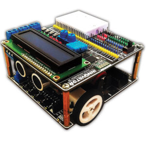
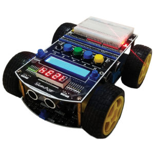

sashikassw (verified owner) –
මේක online order කරලා දවස් දෙකක් යන්නත් කලින් මට ලැබුනා . හොඳට pack කරලා නියම ආරක්ෂිත විදිහටම එවලා තිබුනා.ඉතාමත්ම වටිනා වැදගත් නිෂ්පාදනයක් . මම Arduino වලට ආධුනිකයෙක්. Bred board එකෙන් Circuit check කරන කොට ඒක වැඩ නොකරන්න තියන හැකියාව වැඩියි. ඒ උනාට මේ board එකේ අපිට අවශ්යය sensor, LED, Buttons සේරම තියනවා (ඊට අමතරව තවත් options විශාල ප්රමාණයක් තියනවා ). වෙනම power දෙන්න ඕනෙත් නෑ. ඒක නිසා wire අවශ්යය වෙන්නේ data වලට විතරයි. ඒක මාරම පහසුයි මේ board එකත් එක්ක වැඩ කරන්න . හොඳ නිමවුමක් සහිතව හැමදෙයක්ම පැහැදිලිව නම් කරලා තියනවා .පාසල් වලට , කාර්මික විද්යාල වලට , විශ්ව විද්යාල වලටත් මේකේ වටිනාකම කියා නිමකරන්න බැරි වේවි. අනික ශ්රී ලාංකිකයෙක් මේ වගේ දෙයක් කිරීම මම ගොඩක් අගය කරනවා .තව තවත් මේ වගේ වටිනා දේවල් නිෂ්පාදනය කරන්න ලැබේවායි මම ඔබට සුබ පතනවා.