Description
- Description
- Downloads
- Examples
- Projects
- Package Includes
Inspire - Arduino compatible and Customizable embedded development environment
This is a special well designed compact platform for Arduino and mobile robot
development which could be used for educational or development purposes.
Specifically this has two compartments, one is a development platform and the second
is mobile robot platform . This development platform provides space for development
purposes with Arduino. The two main compartments could work individually or as a combination.
Built in components
Features
Specifications
Top Development Board :
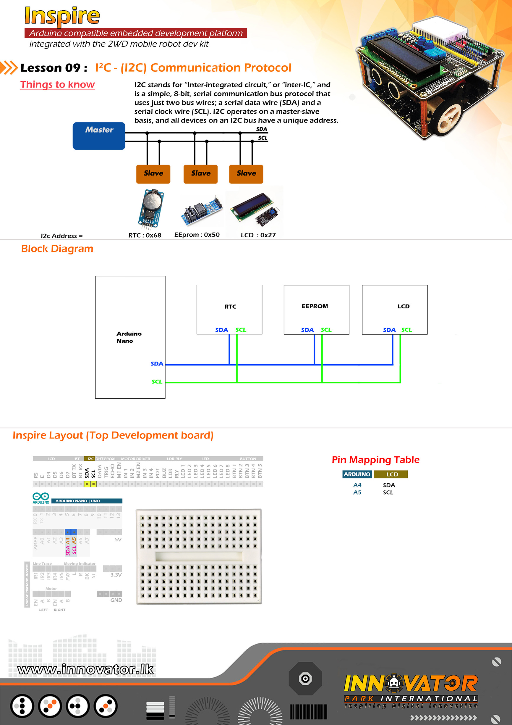
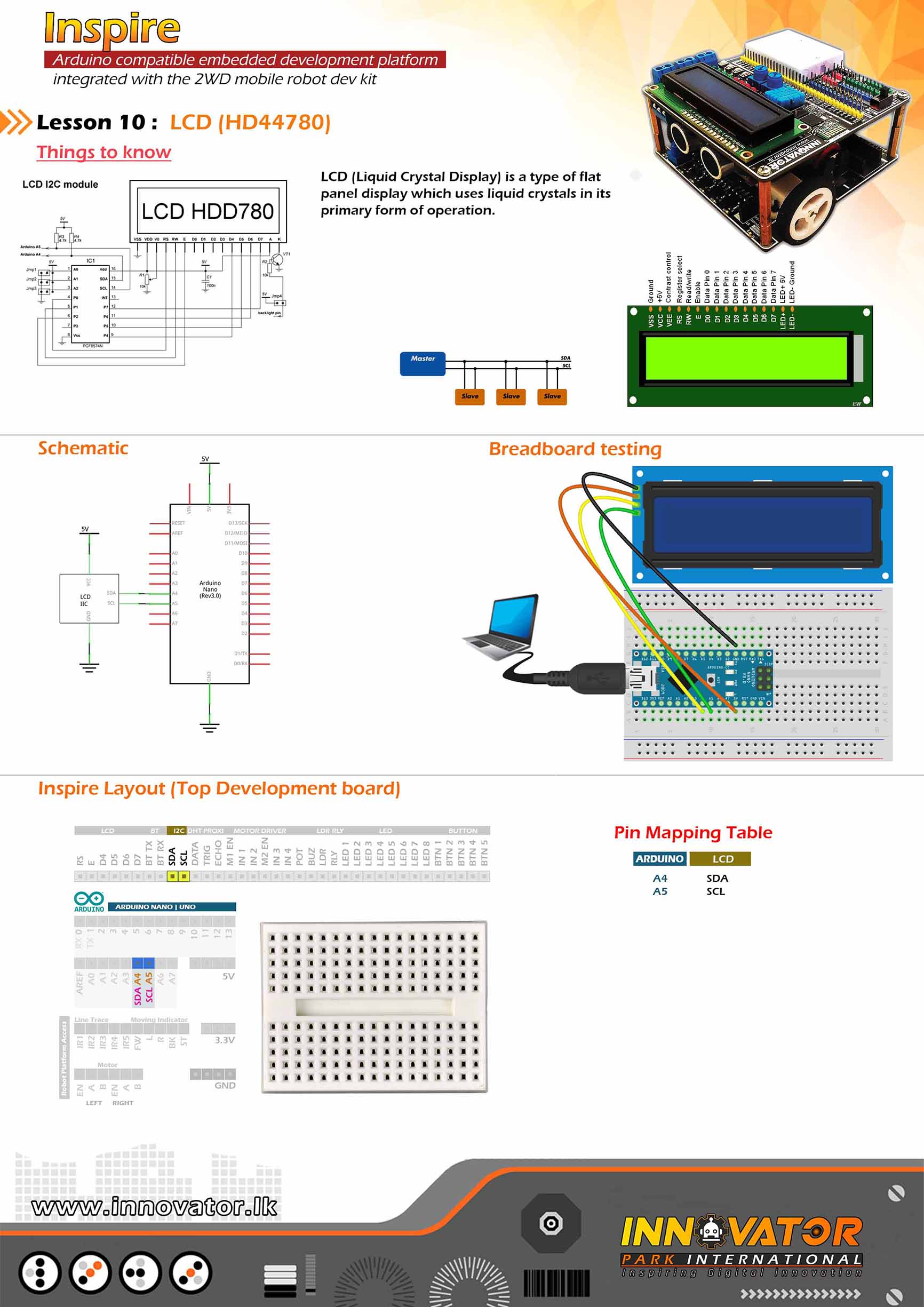
- 16x2 Character (hd44780) LCD (standard driving interface & I2C capable).
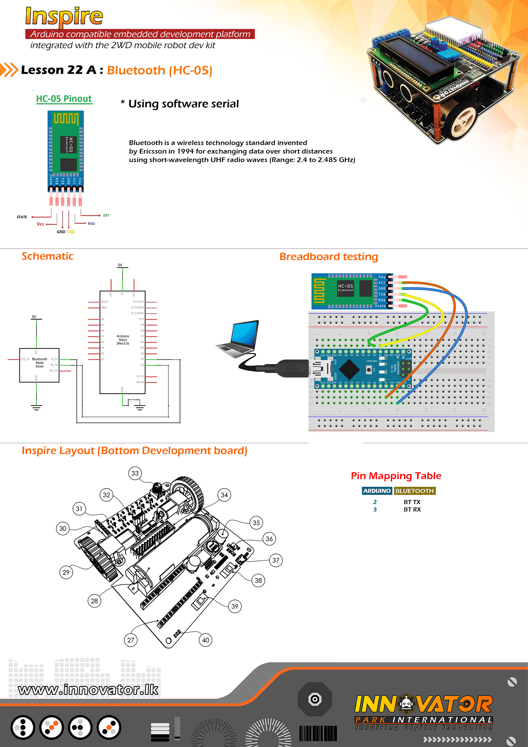
- HC-05 Bluetooth module with level converter.
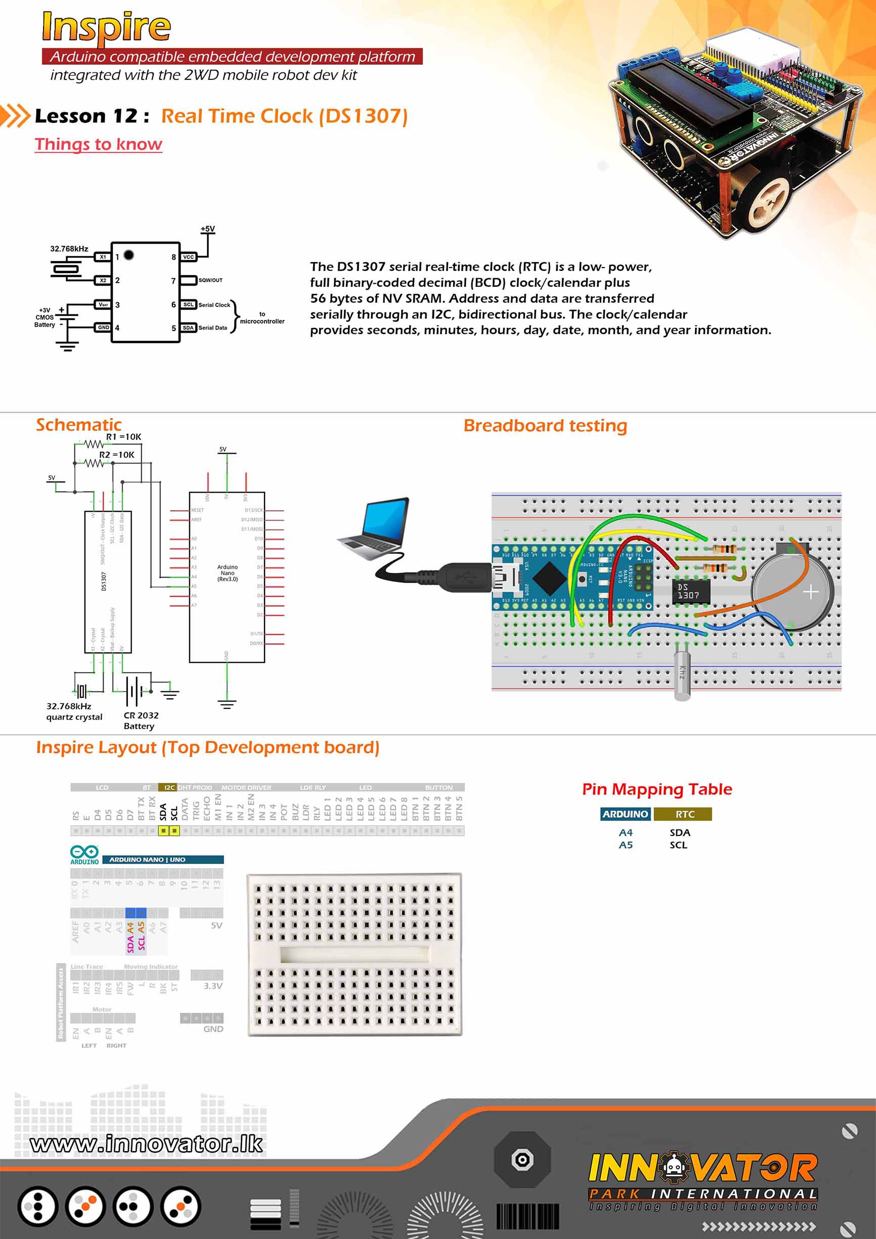
- Real-time clock module (1307).
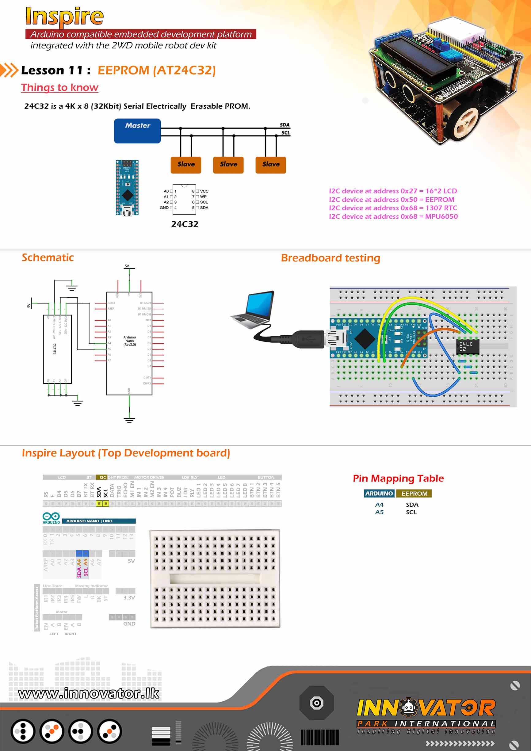
- EEPROM 24C32.
- DHT 11 Humidity & Temperature Sensors.
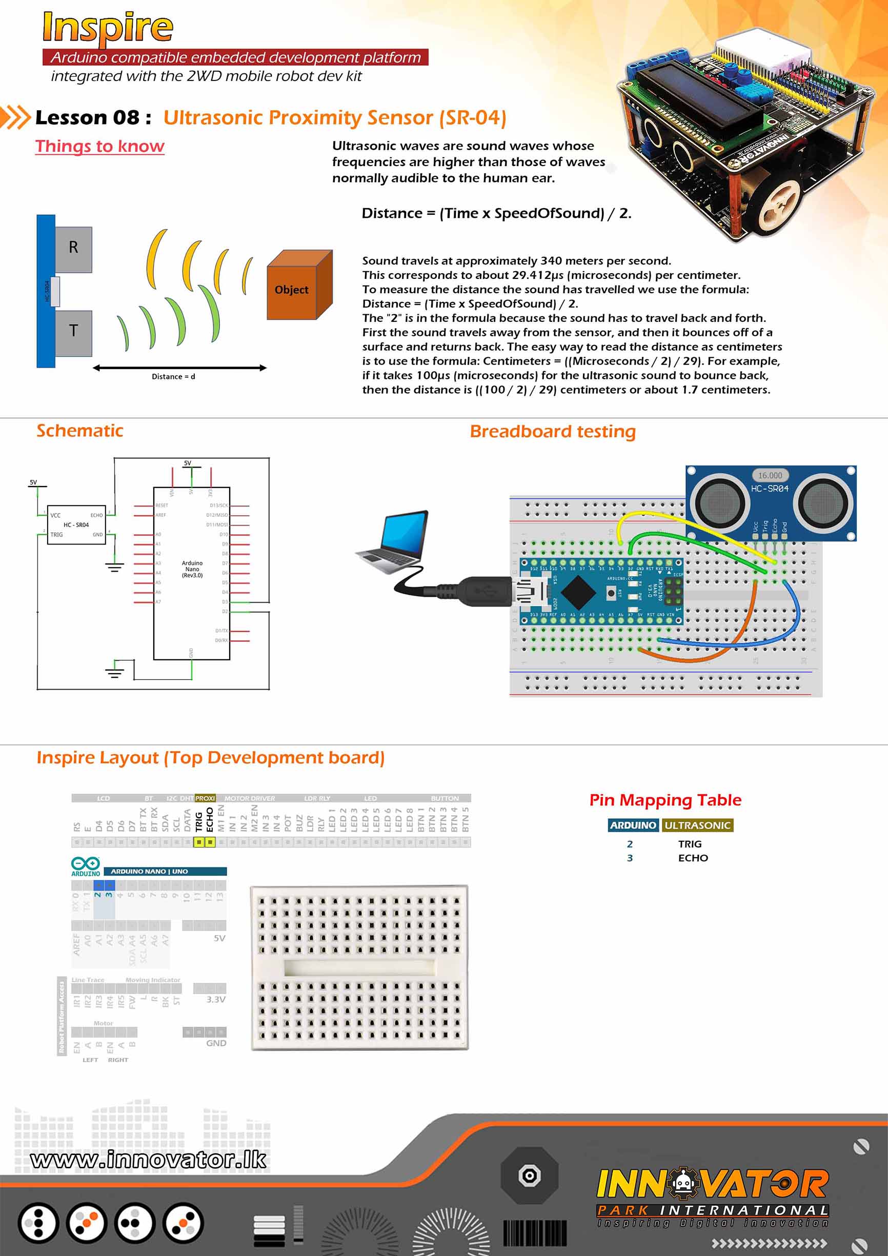
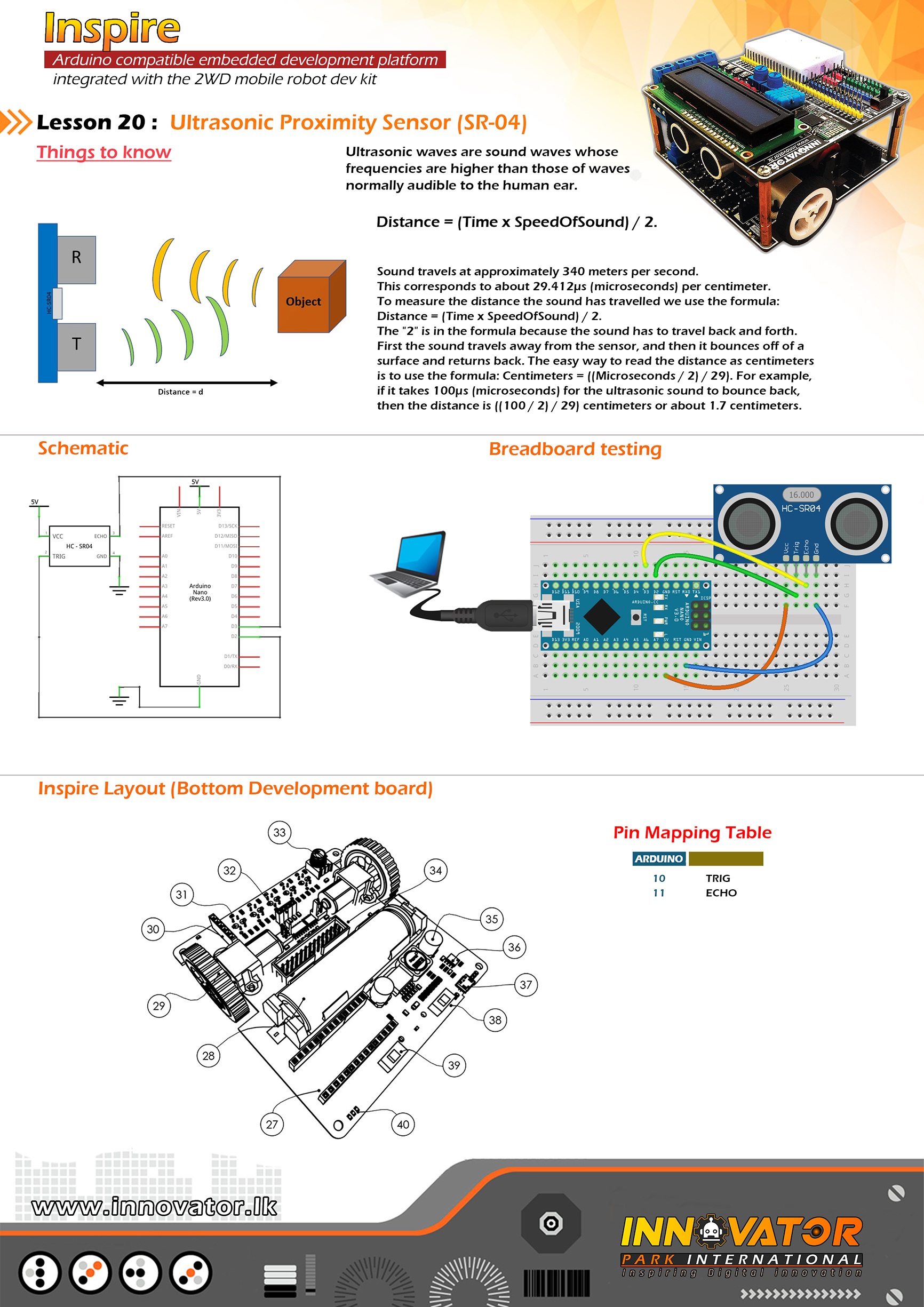
- HC-SR04 Ultrasonic distance sensor.
- Motor driver L293D.
- 8x LEDs (4 red & 4 green).
- Potentiometer (10K).
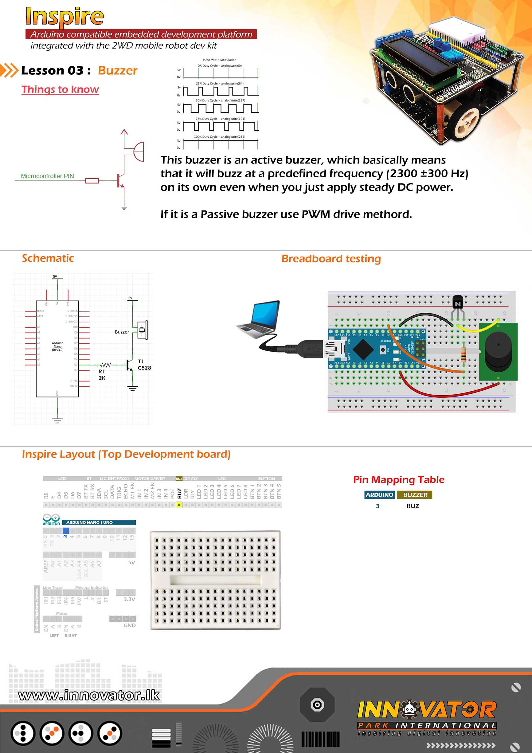
- 5v Active buzzer with driver circuit.
- Relay driver with 5v 10A relay.
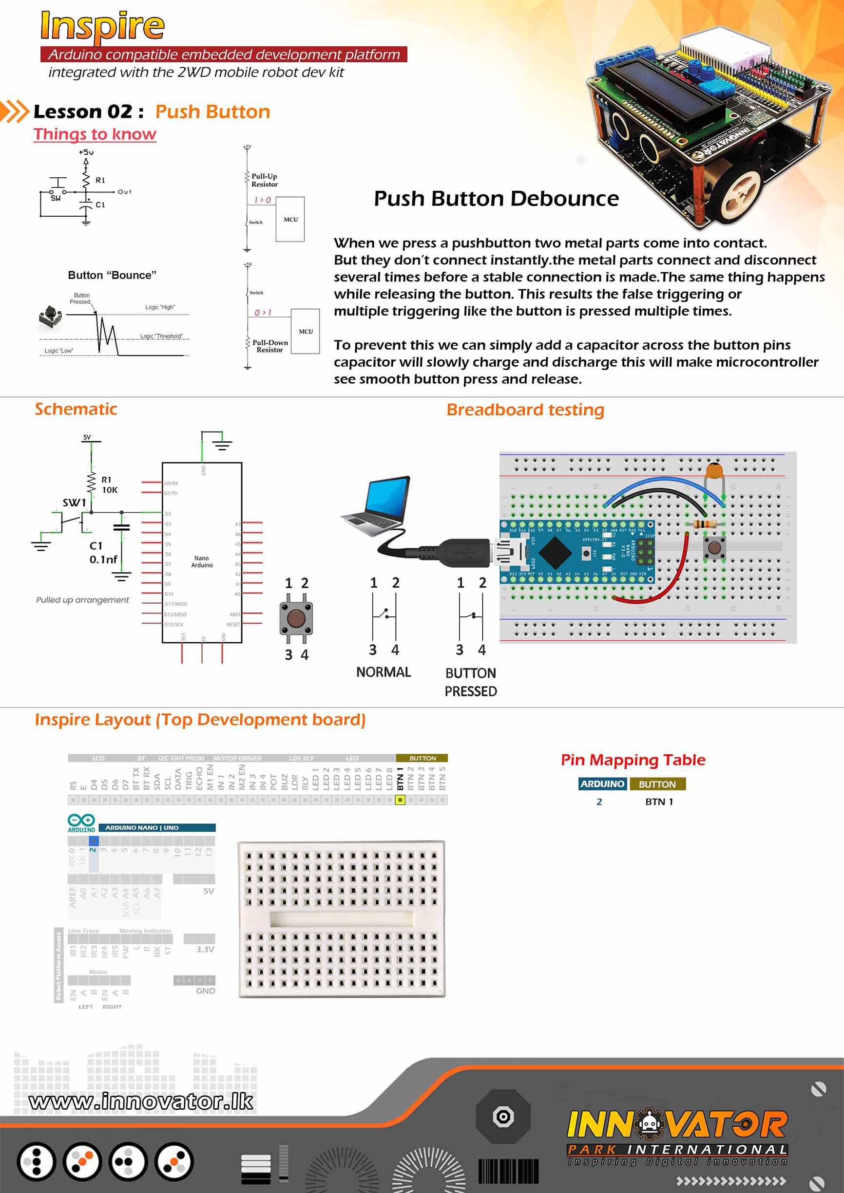
- 5x Push buttons (pulled-up).
- light dependent resistor(LDR).
- Mini breadboard (46mm x 36mm x 10mm).
Bottom Development Board :
- 5bit (TCRT5000) Line following sensors.
- TP4056 Battery charging circuit.
- 18650 4200mAH battery.
- CR2032 coin cell battery.
- LED Direction Indicators.
- 2 x N20 Micro gear motors.
Top Development Board :
- Arduino UNO & Nano compatible.
- LCD contrast adjust-ability.
- Platform power on/off switch.
- Power rail: 5v & 3.3v.
- Robot platform accessibility.
- Common reset button.
Bottom Development Board :
- Arduino Nano board plugin capability.
- HC-05, HC-06 Bluetooth module plugin capability.
- HC-SR04 Ultrasonic module plugin capability.
- Motor driver power on/off switch.
- Platform power on/off switch.
- Rechargeable via USB or 5v power source.
- Exposed pins.
- Product Dimensions : 100L x 100W x 60H mm.
- Net Weight : 300g.
- Gross weight : 620g.

/*
  INNOVATOR INTERNATIONAL (PVT)LTD.
  https://www.innovator.lk/
  --------------------------------------------------------
  Development Platform : Inspire 1.0
  (Arduino development platform)
  --------------------------------------------------------
  LED Blink Example.
  --------------------------------------------------------
  Hardware setup :
  Connect LED1 PIN to Arduino Digital PIN-> 2(D2)
  --------------------------------------------------------
  22 march 2021
*/
int LED1 = 2;// the number of the LED 1 pin.

void setup() {
  pinMode(LED1, OUTPUT);//initializing LED1 pin as a output pin.
}

void loop() {
  digitalWrite(LED1, HIGH);//turning on the led.

  delay(1000);//waiting for one second to be elapsed.

  digitalWrite(LED1, LOW);//turning off the led.

  delay(1000);//waiting for one second to be elapsed.
}
/*
  INNOVATOR INTERNATIONAL (PVT)LTD.
  https://www.innovator.lk/
  ------------------------------------------------------------------
  Development Platform : Inspire 1.0
  (Arduino development platform)
  ------------------------------------------------------------------
  Push Button Example.
  ------------------------------------------------------------------
  Hardware setup :
  plug a Arduino nano board in to the inspre top development board.
  turn on power switch of the top development board.

  connect BTN1 PIN to Arduino Digital PIN-> 2(D2)
  ------------------------------------------------------------------
  22 march 2021
*/

int BUTTON1 = 2;//the number of the push button PIN.
int BUTTON1_STATE = 1;//a variable to hold the button state.

void setup() {
  Serial.begin(9600);//starting serial communication between arduino and computer.

  pinMode(BUTTON1, INPUT);//initializing BUTTON PIN as a input PIN.
}

void loop() {
  BUTTON1_STATE = digitalRead(BUTTON1);//read the state of the push button value.

  if ( BUTTON1_STATE == false) {//check if the value of the variable is equal to 0.

    Serial.println("Button one Pressed !");//if value of the variable 0,then print a message to serial monitor.

    delay(100);//wait some time.
  }
}
/*
  INNOVATOR INTERNATIONAL (PVT)LTD.
  https://www.innovator.lk/
  -------------------------------------------------------------------
  Development Platform : Inspire 1.0
  (Arduino development platform)
  -------------------------------------------------------------------
  Buzzer Example.
  -------------------------------------------------------------------
  Hardware setup :
  plug a Arduino nano board in to the inspre top development board.
  turn on power switch of the top development board.

  Connect BUZ PIN to Arduino Digital PIN-> 2(D2)
  -------------------------------------------------------------------
  22 march 2021
*/

int BUZZER = 2;//the number of the buzzer PIN.

void setup() {
  pinMode(BUZZER, OUTPUT);//initializing BUZZER PIN as a output PIN.
}

void loop() {
  digitalWrite(BUZZER, HIGH);//turning on the buzzer.

  delay(1000);//waiting for one second to be elapsed.

  digitalWrite(BUZZER, LOW);//turning off the buzzer.

  delay(1000);//waiting for one second to be elapsed.
}
/*
INNOVATOR INTERNATIONAL (PVT)LTD.
https://www.innovator.lk/
------------------------------------------------------------------
Development Platform : Inspire 1.0
(Arduino development platform)
------------------------------------------------------------------
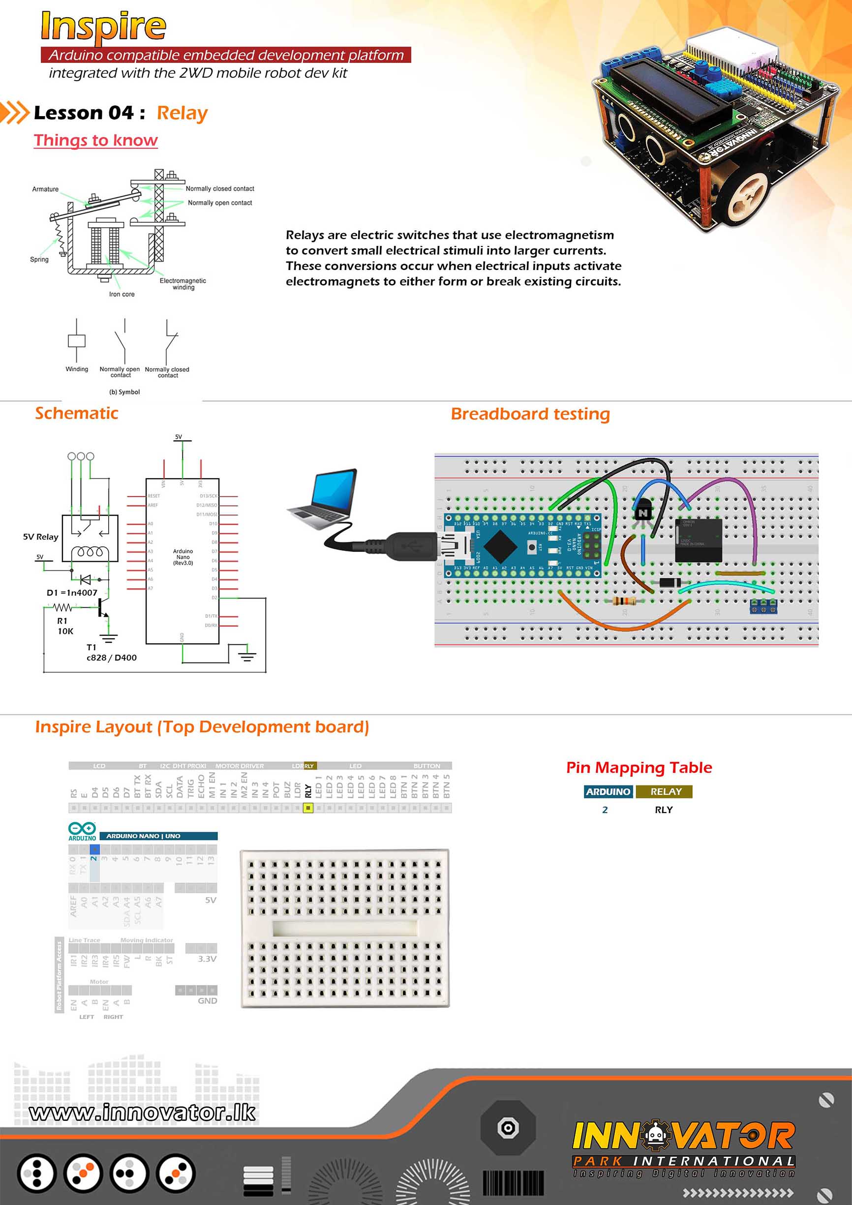
Relay Example.
------------------------------------------------------------------
Hardware setup :
plug a Arduino nano board in to the inspre top development board.
turn on power switch of the top development board.
connect RLY PIN to Arduino Digital PIN-> 2(D2)
------------------------------------------------------------------
22 march 2021
*/
int RELAY = 2;// the number of the RELAY pin.
void setup() {
pinMode(RELAY, OUTPUT);//initializing RELAY pin as a output pin.
}
void loop() {
digitalWrite(RELAY, HIGH);//turning on the relay.
delay(1000);//waiting for one second to be elapsed.
digitalWrite(RELAY, LOW);//turning off the relay.
delay(1000);//waiting for one second to be elapsed.
}
/*
INNOVATOR INTERNATIONAL (PVT)LTD.
https://www.innovator.lk/
------------------------------------------------------------------
Development Platform : Inspire 1.0
(Arduino development platform)
------------------------------------------------------------------
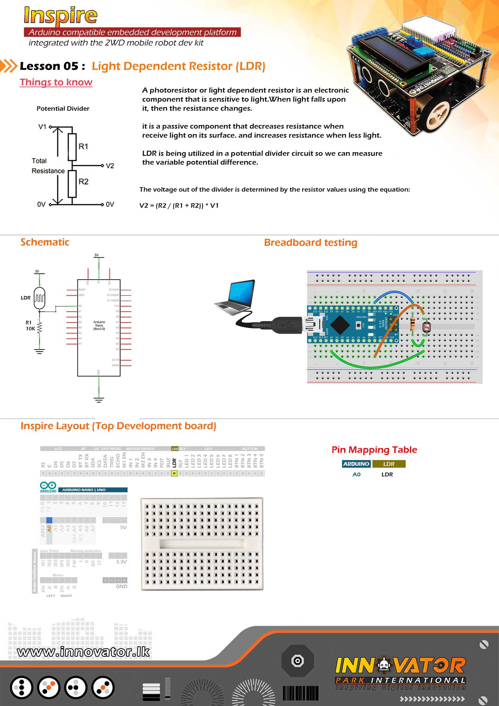
LDR Example.
------------------------------------------------------------------
Hardware setup :
plug a Arduino nano board in to the inspre top development board.
turn on power switch of the top development board.
Connect LDR PIN to Arduino Analog PIN-> 0(A0)
------------------------------------------------------------------
22 march 2021
*/
int LDR = A0;// the number of the LDR pin.
void setup() {
Serial.begin(9600);//starting serial communication between arduino and computer.
pinMode(LDR, INPUT);//initializing LDR PIN as a input PIN.
}
void loop() {
int LDR_VALUE = analogRead(LDR);//read and store the value of the LDR PIN in the variable called "LDR_VALUE".
Serial.println(LDR_VALUE);//printing the value of "LDR_VALUE" variable to the serial monitor.
delay(1000);//waiting for one second to be elapsed.
}
/*
INNOVATOR INTERNATIONAL (PVT)LTD.
https://www.innovator.lk/
-------------------------------------------------------------------
Development Platform : Inspire 1.0
(Arduino development platform)
-------------------------------------------------------------------
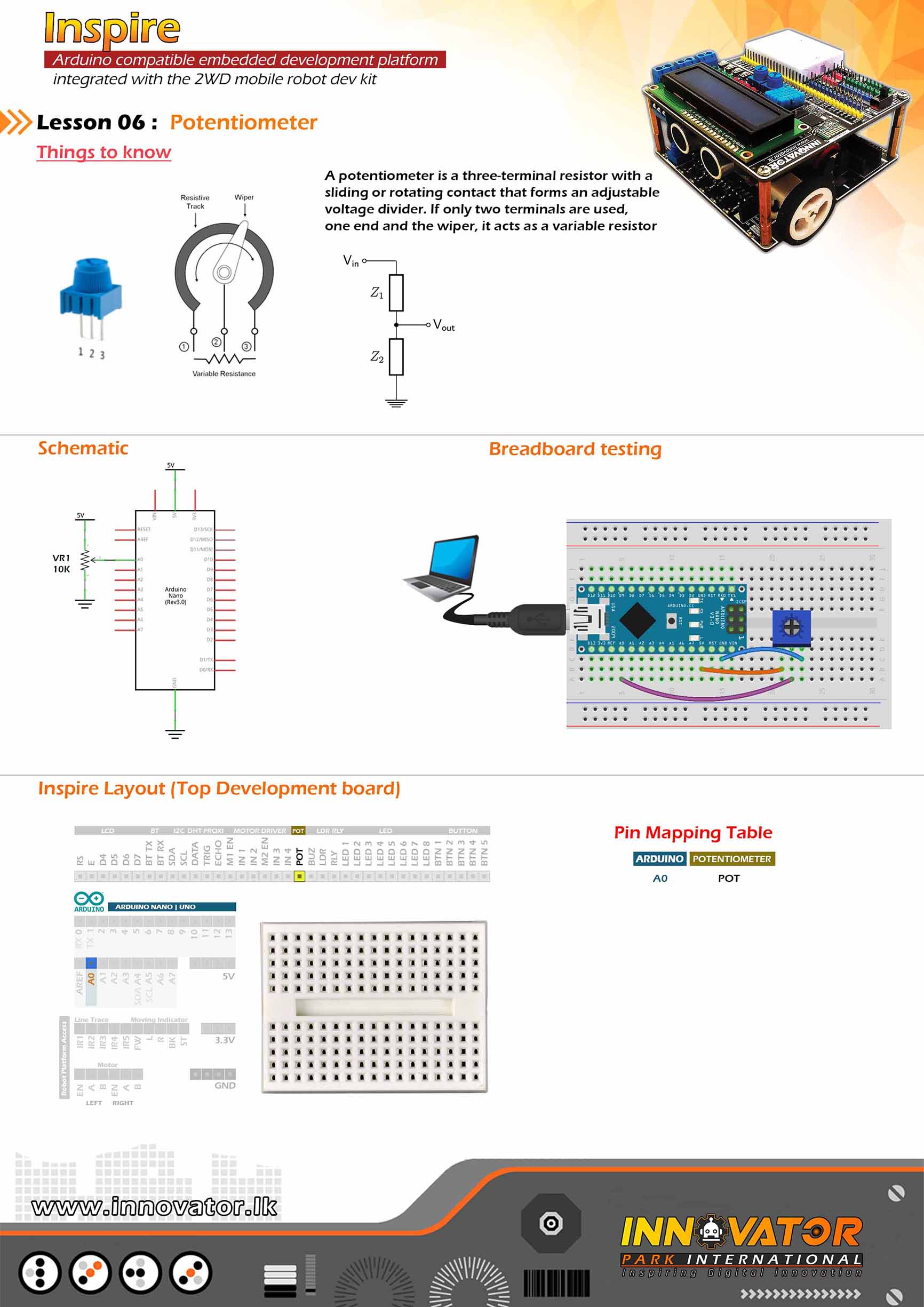
PotentioMeter Example.
-------------------------------------------------------------------
Hardware setup :
plug a Arduino nano board in to the inspre top development board.
turn on power switch of the top development board.
Connect POT PIN to Arduino Analog PIN-> 0(A0)
turn on power switch of the top development board.
-------------------------------------------------------------------
22 march 2021
*/
int POTENTIOMETER = A0;//the number of the POT pin.
void setup() {
Serial.begin(9600);//starting serial communication between arduino and computer.
pinMode(POTENTIOMETER, INPUT);//initializing POT pin as a input pin.
}
void loop() {
int POTENTIOMETER_VALUE = analogRead(POTENTIOMETER);//read and store the value of the POT pin in the variable called "POTENTIOMETER_VALUE".
Serial.println(POTENTIOMETER_VALUE);//printing the value of "POTENTIOMETER_VALUE" variable to the serial monitor.
delay(1000);//waiting for one second to be elapsed.
}
/*
INNOVATOR INTERNATIONAL (PVT)LTD.
https://www.innovator.lk/
------------------------------------------------------------------
Development Platform : Inspire 1.0
(Arduino development platform)
------------------------------------------------------------------
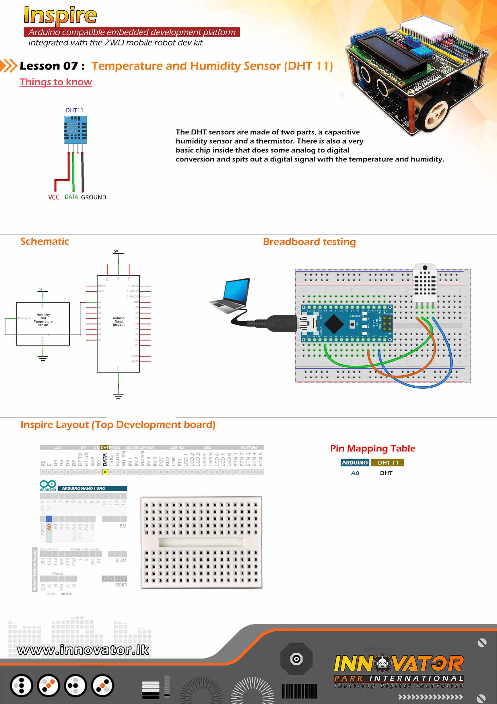
DHT11 Example.
------------------------------------------------------------------
Hardware setup :
plug a Arduino nano board in to the inspre top development board.
turn on power switch of the top development board.
Connect DHT PIN to Arduino analog PIN-> 0(A0)
------------------------------------------------------------------
22 march 2021
*/
#include "DHT.h";//including the DHT sensor library.
int DHTPIN = A0;//the number of the DHT11 DATA pin.
int DHTTYPE = DHT11;//selecting the DHT sensor model.
DHT dht(DHTPIN, DHTTYPE);//initiating a DHT object.
float Humidity;//a variable to hold the humidity value.
float Temperature;//a variable to hold the temperature value.
void setup() {
Serial.begin(9600);//starting serial communication between arduino and computer.
dht.begin();//initiating connection to the DHT sensor.
}
void loop() {
//read data and store it in variables called "Humidity" and "Temperature".
Humidity = dht.readHumidity();
Temperature = dht.readTemperature();
//printing values to the serial monitor.
Serial.print("Humidity: ");
Serial.print(Humidity);
Serial.print(" %, Temp: ");
Serial.print(Temperature);
Serial.println(" Celsius");
delay(2000);//keep a two second delay between each serial print.
}
/*
  INNOVATOR INTERNATIONAL (PVT)LTD.
  https://www.innovator.lk/
  ------------------------------------------------------------------
  Development Platform : Inspire 1.0
  (Arduino development platform)
  ------------------------------------------------------------------
  hc-sr04 Ultrasonic Distance Sensor Example.
  ------------------------------------------------------------------
  Hardware setup :
  plug a Arduino nano board in to the inspre top development board.
  turn on power switch of the top development board.

  connect ECHO PIN to Arduino Digital PIN-> 3(D3)
  connect TRIG PIN to Arduino Digital PIN-> 2(D2)
  ------------------------------------------------------------------
  22 march 2021
*/

int ECHO = 3;// the number of the ECHO pin.

int TRIG = 2;// the number of the TRIG pin.


long duration; //a variable to hold the duration of sound wave travel value.

int distance; //a variable to hold the distance measurement value.

void setup() {
  pinMode(TRIG, OUTPUT); //initializing TRIG pin as a output pin.

  pinMode(ECHO, INPUT); //initializing ECHO pin as a input pin.

  Serial.begin(9600); //starting serial communication between arduino and computer.
}
void loop() {
  // making the TRIG pin LOW for 2 microseconds.
  digitalWrite(TRIG, LOW);
  delayMicroseconds(2);

  // making the TRIG pin HIGH for 10 microseconds.
  digitalWrite(TRIG, HIGH);
  delayMicroseconds(10);
  digitalWrite(TRIG, LOW);

  // reads the ECHO pin value and returns the sound wave travel time in microseconds.
  duration = pulseIn(ECHO, HIGH);
  // calculating the distance.
  distance = duration * 0.034 / 2; //speed of sound wave divided by 2 (to go forward and reflect on something and come back).

  // displays the calculated distance in the serial monitor.
  Serial.print("Distance: ");
  Serial.print(distance);
  Serial.println(" cm");
}
/*
  INNOVATOR INTERNATIONAL (PVT)LTD.
  https://www.innovator.lk/
  ------------------------------------------------------------------
  Development Platform : Inspire 1.0
  (Arduino development platform)
  ------------------------------------------------------------------
  I2C Device Scanning Example.
  ------------------------------------------------------------------
  Hardware setup :
  plug a Arduino nano board in to the inspre top development board.
  turn on power switch of the top development board.

  Connect Arduino analog PIN 4(A4) to I2C SDA PIN
  Connect Arduino analog PIN 5(A5) TO I2C SCL PIN
  ------------------------------------------------------------------
  I2C device at address 0x27 = 16*2 LCD
  I2C device at address 0x50 = EEPROM
  I2C device at address 0x68 = 1307 RTC
  ------------------------------------------------------------------
  22 march 2021
*/

#include "Wire.h" //including the wire library in order to communicate with i2c bus devices.

void setup()
{
  Wire.begin(); //initializing connection to the i2c device(s).

  Serial.begin(9600);//starting serial communication between arduino and computer.

  Serial.println("nI2C Scanner");//printing message to serial monitor.
}


void loop()
{
  byte error, address; //variables to hold the error values and i2c devices addresses.

  int nDevices;//a variable to hold the i2c device count.

  Serial.println("Scanning...");//printing message to serial monitor.

  nDevices = 0;
  for (address = 1; address < 127; address++ )
  {
    // the i2c_scanner uses the return value of
    // the Write.endTransmisstion to see if
    // a device did acknowledge to the address.
    Wire.beginTransmission(address);

    error = Wire.endTransmission();

    if (error == 0)
    {
      Serial.print("I2C device found at address 0x");
      if (address < 16)
        Serial.print("0");
      Serial.print(address, HEX);
      Serial.println("  !");

      nDevices++;
    }
    else if (error == 4)
    {
      Serial.print("Unknown error at address 0x");
      if (address < 16)
        Serial.print("0");
      Serial.println(address, HEX);
    }
  }
  if (nDevices == 0)
    Serial.println("No I2C devices foundn");
  else
    Serial.println("donen");

  delay(5000);// wait 5 seconds between each next scan.
}
/*
  INNOVATOR INTERNATIONAL (PVT)LTD.
  https://www.innovator.lk/
  ------------------------------------------------------------------
  Development Platform : Inspire 1.0
  (Arduino development platform)
  ------------------------------------------------------------------
  HD44780 16*2 LCD Example.
  ------------------------------------------------------------------
  Hardware setup :
  plug a Arduino nano board in to the inspre top development board.
  turn on power switch of the top development board.

  connect Arduino analog PIN 4(A4) to SDA
  connect Arduino analog PIN 5(A5) to SCL
  ------------------------------------------------------------------
  22 march 2021
*/

#include  "LiquidCrystal_I2C.h"//including the LCD driver library.

LiquidCrystal_I2C lcd(0x27, 16, 2);//initializing the LCD I2C address(0x27) and LCD's number of columns(16) and rows(2).

void setup() {
  lcd.begin();//initiating connection to the LCD.

  lcd.backlight();//turning on the backlight of the LCD.

  lcd.setCursor(0, 0);//setting the cursor position to column 0 and row 0.

  lcd.print("Inspire");//printing a message to LCD.

  delay(1000);//waiting for one second to be elapsed.

  lcd.clear();//clearing the charcters printed on the LCD.
}

void loop() {
  lcd.setCursor(2, 0);//setting the cursor position to column 2 and row 0.

  lcd.print("Hello world !");//printing a message to LCD.
}
/*
  INNOVATOR INTERNATIONAL (PVT)LTD.
  https://www.innovator.lk/
  ------------------------------------------------------------------
  Development Platform : Inspire 1.0
  (Arduino development platform)
  ------------------------------------------------------------------
  EEPROM Example.
  ------------------------------------------------------------------
  Hardware setup :
  plug a Arduino nano board in to the inspre top development board.
  turn on power switch of the top development board.

  Connect Arduino analog PIN 4(A4) to I2C SDA PIN
  Connect Arduino analog PIN 5(A5) TO I2C SCL PIN
  ------------------------------------------------------------------
  I2C device at address 0x27 = 16*2 LCD
  I2C device at address 0x50 = EEPROM
  I2C device at address 0x68 = 1307 RTC
  ------------------------------------------------------------------
  22 march 2021
*/

#include "Wire.h"//including wire library, in order to communicate with i2c bus devices.

int EEPROM_I2C_ADDRESS = 0x50;//address of the AT24c32 eeprom chip on i2c bus.

void setup()
{
  Wire.begin();//initiating connection to the i2c devices.

  Serial.begin(9600);//starting serial communication between arduino and computer.

  int address = 0; //starting address in the eeprom.

  byte value = 100; //value to write to the eeprom.

  Serial.println("writing value :100 to eeprom");//printing a message to serial monitor.

  writeAddress(address, value);//writing data to eeprom.

  byte readValue = readAddress(address);//a variable to hold the vale read from eeprom.

  Serial.print("The returned value is ");//printing a message to serial monitor.

  Serial.println(readValue);//printing the value to serial monitor.

}

void loop()
{
  //nothing to do here ;)
}

void writeAddress(int address, byte value)//function to write data to eeprom.
{
  Wire.beginTransmission(EEPROM_I2C_ADDRESS);//starting data transmission with the device at specified address.

  Wire.write((int)(address >> 8));//writing data to (MSB) most significant bit.

  Wire.write((int)(address & 0xFF));//writing data to (LSB) least significant bit.

  Wire.write(value);//writing data to wire.

  Wire.endTransmission();//closing transmition.

  delay(5);//wait for 5 microseconds.
}

byte readAddress(int address)//function to read data from eeprom.
{
  byte rData = 0xFF; // variable to hold the data read from eeprom.

  Wire.beginTransmission(EEPROM_I2C_ADDRESS);//starting data transmission with the device at specified address.

  Wire.write((int)(address >> 8));// writing data to (MSB) most significant bit.

  Wire.write((int)(address & 0xFF));//writing data to (LSB) least significant bit.

  Wire.endTransmission();//closing transmission.

  Wire.requestFrom(EEPROM_I2C_ADDRESS, 1);//reqesting data.

  rData =  Wire.read(); // reading data from eeprom and storing data in the variable.

  return rData;//returning stored value.
}
/*
  INNOVATOR INTERNATIONAL (PVT)LTD.
  https://www.innovator.lk/
  ------------------------------------------------------------------
  Development Platform : Inspire 1.0
  (Arduino development platform)
  ------------------------------------------------------------------
  RTC Example.
  ------------------------------------------------------------------
  Hardware setup :
  plug a Arduino nano board in to the inspre top development board.
  turn on power switch of the top development board.

  Connect Arduino analog PIN 4(A4) to I2C SDA PIN
  Connect Arduino analog PIN 5(A5) TO I2C SCL PIN
  ------------------------------------------------------------------
  I2C device at address 0x27 = 16*2 LCD
  I2C device at address 0x50 = EEPROM
  I2C device at address 0x68 = 1307 RTC
  ------------------------------------------------------------------
  22 march 2021
*/
#include "Wire.h"//including wire library in order to communicate with i2c bus devices.

#include "RTClib.h"//including real time clock library in order to use its functions.

RTC_DS1307 rtc;//creating a rtc object.


char daysOfTheWeek[7][12] = {"Sunday", "Monday", "Tuesday", "Wednesday", "Thursday", "Friday", "Saturday"};//char array for storing the days of a week.


void setup () {

  Serial.begin(9600);//starting serial communication between arduino and computer.

  if (! rtc.begin()) {//check if we can connect to the rtc module.

    Serial.println("Couldn't find RTC");//if we can't connect to rtc module, print a message to serial monitor.

    while (1);//keep checking until we are able to connect to the rtc module.
  }
  if (! rtc.isrunning()) {//check if rtc is running.

    Serial.println("RTC is NOT running!");//else print message to the serial monitor.

    rtc.adjust(DateTime(2021, 3, 22, 10, 00, 0));//adjusting date and time.
  }
}
void loop () {
  DateTime now = rtc.now(); //obtaining current the date and time.

  //printing all information to serial monitor.
  Serial.print(now.year(), DEC);
  Serial.print('/');
  Serial.print(now.month(), DEC);
  Serial.print('/');
  Serial.print(now.day(), DEC);
  Serial.print(" (");
  Serial.print(daysOfTheWeek[now.dayOfTheWeek()]);//obtaining the day of the week from the "daysOfTheWeek" array.
  Serial.print(") ");
  Serial.print(now.hour(), DEC);
  Serial.print(':');
  Serial.print(now.minute(), DEC);
  Serial.print(':');
  Serial.print(now.second(), DEC);
  Serial.println();

  delay(3000);//keep a 3 second time delay between each serial print.
}
/*
INNOVATOR INTERNATIONAL (PVT)LTD.
https://www.innovator.lk/
-----------------------------------------------------------------------------
Development Platform : Inspire 1.0
(Arduino development platform)
-----------------------------------------------------------------------------
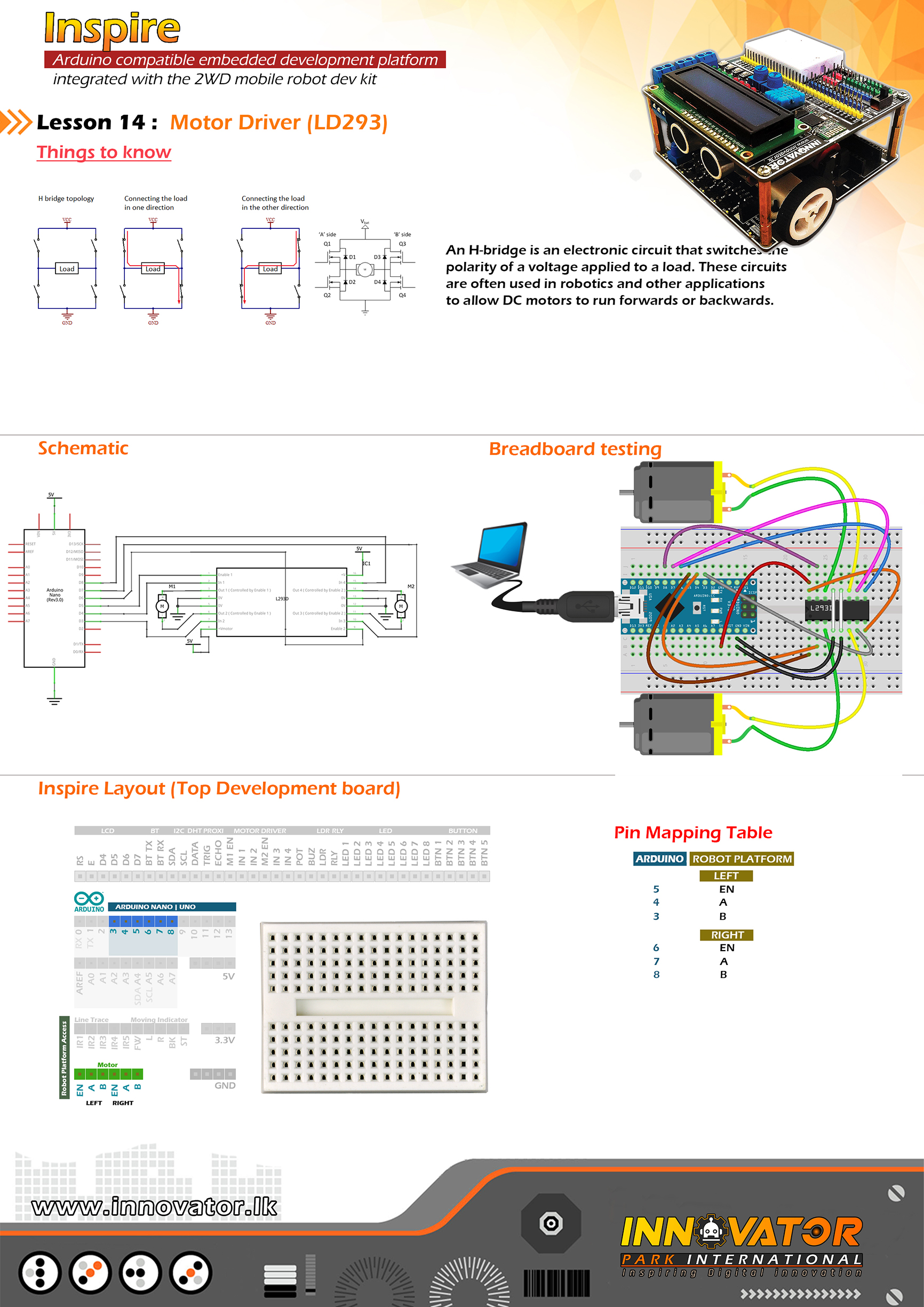
Motor Driver Example(Top Board).
-----------------------------------------------------------------------------
Hardware setup :
plug a Arduino nano board in to the inspre top development board.
turn on both power switchs of the top development board & bottom one.
--------------------------------left motor----------------------------------
connect LEFT EN to Arduino Digital PIN-> 5(D5)
connect LEFT A to Arduino Digital PIN-> 4(D4)
connect LEFT B to Arduino Digital PIN-> 3(D3)
--------------------------------right motor----------------------------------
connect RIGHT EN to Arduino Analog PIN-> 6(D6)
connect RIGHT A to Arduino Digital PIN-> 7(D7)
connect RIGHT B to Arduino Digital PIN-> 8(D8)
----------------------------------------------------------------------------
22 march 2021
*/
int LEFT_EN = 5; //initializing LEFT_EN pin as a output pin.
int LEFT_A = 3;//initializing LEFT_A pin as a output pin.
int LEFT_B = 4;//initializing LEFT_B pin as a output pin.
int RIGHT_EN = 6;//initializing RIGHT_EN pin as a output pin.
int RIGHT_A = 7;//initializing RIGHT_A pin as a output pin.
int RIGHT_B = 8;//initializing RIGHT_B pin as a output pin.
void setup() {
// initializing all the motor control pins to be outputs.
pinMode(LEFT_EN, OUTPUT);
pinMode(RIGHT_EN, OUTPUT);
pinMode(LEFT_A, OUTPUT);
pinMode(LEFT_B, OUTPUT);
pinMode(RIGHT_A, OUTPUT);
pinMode(RIGHT_B, OUTPUT);
// turning off all motors.
digitalWrite(LEFT_A, LOW);
digitalWrite(LEFT_B, LOW);
digitalWrite(RIGHT_A, LOW);
digitalWrite(RIGHT_B, LOW);
}
void loop() {
directionControl(); // drive motors back and forth.
delay(1000);//waiting for one second to be elapsed.
speedControl();//controling the seed of the motors.
delay(1000);//waiting for one second to be elapsed.
}
void directionControl() {
// set motors to maximum speed.
// PWM maximum possible values are 0 to 255.
analogWrite(LEFT_EN, 255);
analogWrite(RIGHT_EN, 255);
//left mortor foward
digitalWrite(LEFT_A, HIGH);
digitalWrite(LEFT_B, LOW);
//---------------------------------
//right mortor backward
digitalWrite(RIGHT_A, HIGH);
digitalWrite(RIGHT_B, LOW);
//---------------------------------
delay(2000);
//---------------------------------
// changing motor directions.
//left mortor backward
digitalWrite(LEFT_A, LOW);
digitalWrite(LEFT_B, HIGH);
//---------------------------------
//right mortor foward
digitalWrite(RIGHT_A, LOW);
digitalWrite(RIGHT_B, HIGH);
//---------------------------------
delay(2000);
//---------------------------------
// turn off all motors.
digitalWrite(LEFT_A, LOW);
digitalWrite(LEFT_B, LOW);
digitalWrite(RIGHT_A, LOW);
digitalWrite(RIGHT_B, LOW);
}
void speedControl() {
// turn on motors
digitalWrite(LEFT_A, LOW);
digitalWrite(LEFT_B, HIGH);
digitalWrite(RIGHT_A, LOW);
digitalWrite(RIGHT_B, HIGH);
// accelerate from zero to maximum speed.
for (int i = 0; i < 256; i++) { analogWrite(LEFT_EN, i); analogWrite(RIGHT_EN, i); delay(20); } // de-accelerate from maximum speed to zero. for (int i = 255; i >= 0; --i) {
analogWrite(LEFT_EN, i);
analogWrite(RIGHT_EN, i);
delay(20);
}
// turning off all motors.
digitalWrite(LEFT_A, LOW);
digitalWrite(LEFT_B, LOW);
digitalWrite(RIGHT_A, LOW);
digitalWrite(RIGHT_B, LOW);
}
/*
INNOVATOR INTERNATIONAL (PVT)LTD.
https://www.innovator.lk/
----------------------------------------------------------------------------
Development Platform : Inspire 1.0
(Arduino development platform)
----------------------------------------------------------------------------
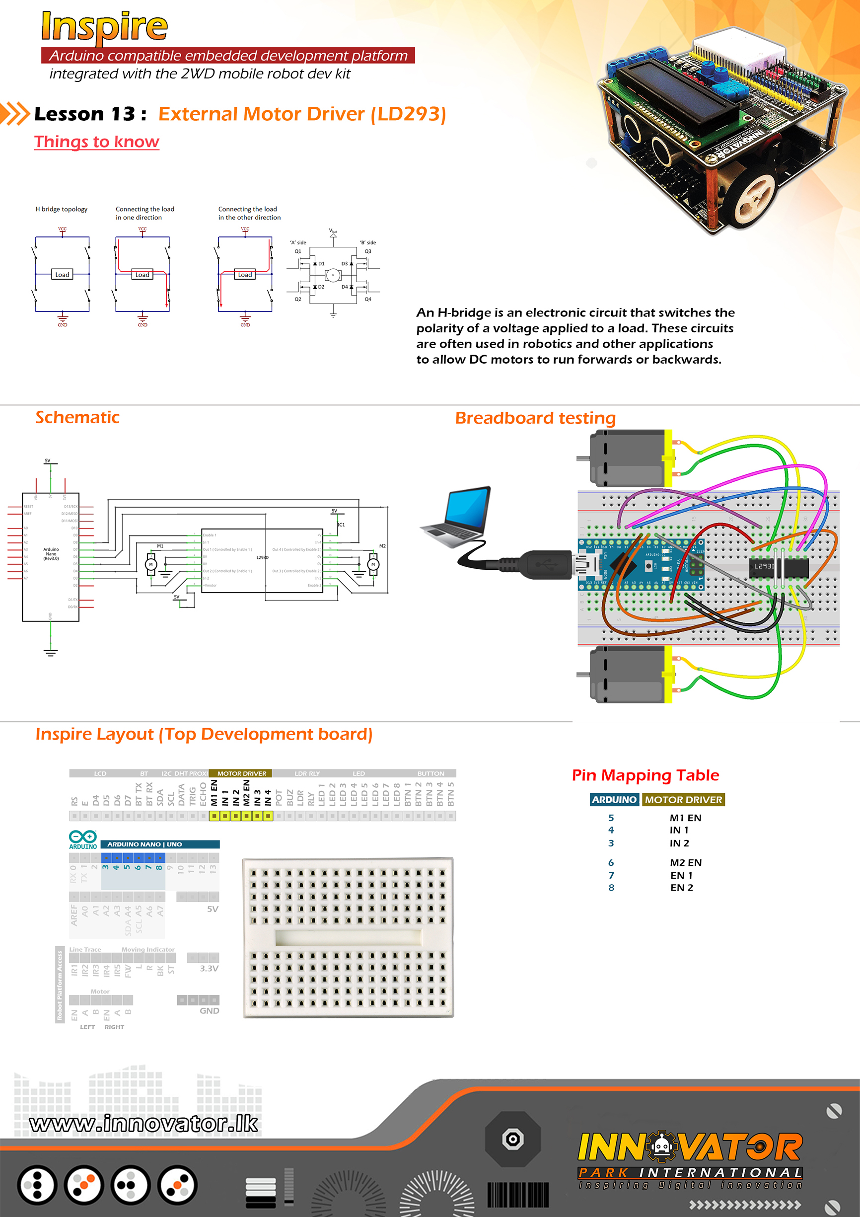
External Motor Driver Example(Top Board).
----------------------------------------------------------------------------
Hardware setup :
plug a Arduino nano board in to the inspre bottom development board.
turn on both power & motor power switchs of the bottom development board.
--------------------------------left motor----------------------------------
Connect M1EN to Arduino digital PIN-> 5(D5)
Connect IN1 to Arduino digital PIN-> 3(D3)
Connect IN2 to Arduino digital PIN-> 4(D4)
--------------------------------right motor---------------------------------
Connect M2EN to Arduino digital PIN-> 6(D6)
Connect IN3 to Arduino digital PIN-> 7(D7)
Connect IN4 to Arduino Digital PIN-> 8(D8)
----------------------------------------------------------------------------
22 march 2021
*/
int M1EN = 5; //initializing M1EN pin as a output pin.
int IN1 = 3;//initializing IN1 pin as a output pin.
int IN2 = 4;//initializing IN2 pin as a output pin.
int M2EN = 6;//initializing M2EN pin as a output pin.
int IN3 = 7;//initializing IN3 pin as a output pin.
int IN4 = 8;//initializing IN4 pin as a output pin.
void setup() {
// initializing all the motor control pins to be outputs.
pinMode(M1EN, OUTPUT);
pinMode(M2EN, OUTPUT);
pinMode(IN1, OUTPUT);
pinMode(IN2, OUTPUT);
pinMode(IN3, OUTPUT);
pinMode(IN3, OUTPUT);
// turning off all motors.
digitalWrite(IN1, LOW);
digitalWrite(IN2, LOW);
digitalWrite(IN3, LOW);
digitalWrite(IN4, LOW);
}
void loop() {
directionControl(); // drive motors back and forth.
delay(1000);//waiting for one second to be elapsed.
speedControl();//controling the seed of the motors.
delay(1000);//waiting for one second to be elapsed.
}
void directionControl() {
// set motors to maximum speed.
// PWM maximum possible values are 0 to 255.
analogWrite(M1EN, 255);
analogWrite(M2EN, 255);
// turning on motor 1 and 2.
digitalWrite(IN1, HIGH);
digitalWrite(IN2, LOW);
digitalWrite(IN3, HIGH);
digitalWrite(IN4, LOW);
delay(2000);
// changing motor directions.
digitalWrite(IN1, LOW);
digitalWrite(IN2, HIGH);
digitalWrite(IN3, LOW);
digitalWrite(IN4, HIGH);
delay(2000);
// turn off all motors.
digitalWrite(IN1, LOW);
digitalWrite(IN2, LOW);
digitalWrite(IN3, LOW);
digitalWrite(IN4, LOW);
}
void speedControl() {
// turn on motors
digitalWrite(IN1, LOW);
digitalWrite(IN2, HIGH);
digitalWrite(IN3, LOW);
digitalWrite(IN4, HIGH);
// accelerate from zero to maximum speed.
for (int i = 0; i < 256; i++) { analogWrite(M1EN, i); analogWrite(M2EN, i); delay(20); } // de-accelerate from maximum speed to zero. for (int i = 255; i >= 0; --i) {
analogWrite(M1EN, i);
analogWrite(M2EN, i);
delay(20);
}
// turning off all motors.
digitalWrite(IN1, LOW);
digitalWrite(IN2, LOW);
digitalWrite(IN3, LOW);
digitalWrite(IN4, LOW);
}
/*
INNOVATOR INTERNATIONAL (PVT)LTD.
https://www.innovator.lk/
----------------------------------------------------------------------------
Development Platform : Inspire 1.0
(Arduino development platform)
----------------------------------------------------------------------------
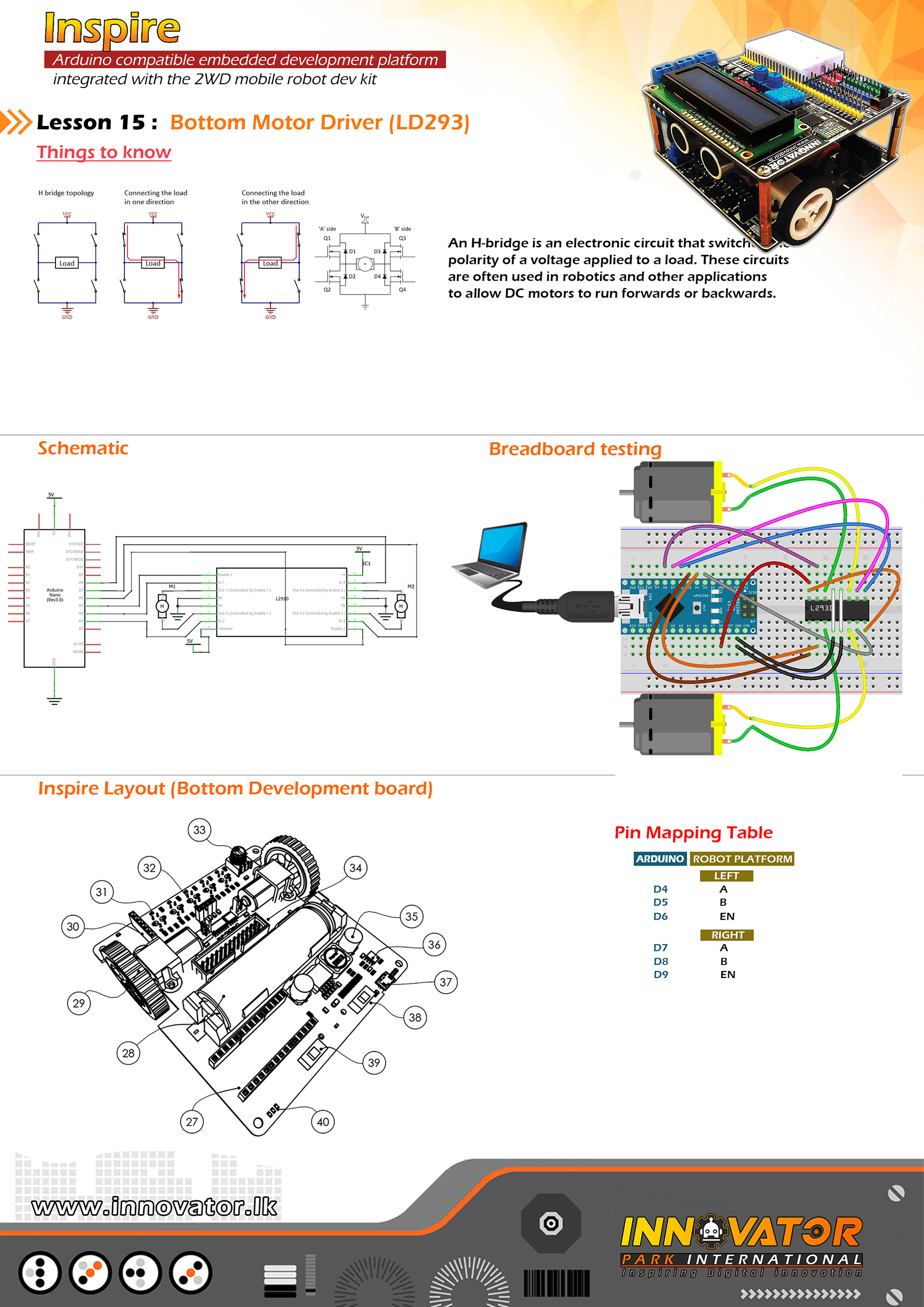
Motor Driver Example(Bottom Board).
----------------------------------------------------------------------------
Hardware setup :
plug a Arduino nano board in to the inspre bottom development board.
turn on both power & motor power switchs of the bottom development board.
--------------------------------left motor----------------------------------
Connect LEFT MOTOR EN to Arduino digital PIN-> 5(D5)
Connect LEFT MOTOR A to Arduino digital PIN-> 4(43)
Connect LEFT MOTOR B to Arduino digital PIN-> 3(D3)
--------------------------------right motor---------------------------------
Connect RIGHT MOTOR EN to Arduino digital PIN-> 6(D6)
Connect RIGHT MOTOR A to Arduino digital PIN-> 7(D7)
Connect RIGHT MOTOR B to Arduino Digital PIN-> 8(D8)
----------------------------------------------------------------------------
22 march 2021
*/
int LEFT_MOTOR_EN = 5; //initializing LEFT_MOTOR_EN pin as a output pin.
int LEFT_MOTOR_A = 3;//initializing LEFT_MOTOR_A pin as a output pin.
int LEFT_MOTOR_B = 4;//initializing LEFT_MOTOR_B pin as a output pin.
int RIGHT_MOTOR_EN = 6;//initializing RIGHT_MOTOR_EN pin as a output pin.
int RIGHT_MOTOR_A = 7;//initializing RIGHT_MOTOR_A pin as a output pin.
int RIGHT_MOTOR_B = 8;//initializing RIGHT_MOTOR_B pin as a output pin.
void setup() {
// initializing all the motor control pins to be outputs.
pinMode(LEFT_MOTOR_EN, OUTPUT);
pinMode(RIGHT_MOTOR_EN, OUTPUT);
pinMode(LEFT_MOTOR_A, OUTPUT);
pinMode(LEFT_MOTOR_B, OUTPUT);
pinMode(RIGHT_MOTOR_A, OUTPUT);
pinMode(RIGHT_MOTOR_A, OUTPUT);
// turning off all motors.
digitalWrite(LEFT_MOTOR_A, LOW);
digitalWrite(LEFT_MOTOR_B, LOW);
digitalWrite(RIGHT_MOTOR_A, LOW);
digitalWrite(RIGHT_MOTOR_B, LOW);
}
void loop() {
directionControl(); // drive motors back and forth.
delay(1000);//waiting for one second to be elapsed.
speedControl();//controling the seed of the motors.
delay(1000);//waiting for one second to be elapsed.
}
void directionControl() {
// set motors to maximum speed.
// PWM maximum possible values are 0 to 255.
analogWrite(LEFT_MOTOR_EN, 255);
analogWrite(RIGHT_MOTOR_EN, 255);
// turning on motor 1 and 2.
digitalWrite(LEFT_MOTOR_A, HIGH);
digitalWrite(LEFT_MOTOR_B, LOW);
digitalWrite(RIGHT_MOTOR_A, HIGH);
digitalWrite(RIGHT_MOTOR_B, LOW);
delay(2000);
// changing motor directions.
digitalWrite(LEFT_MOTOR_A, LOW);
digitalWrite(LEFT_MOTOR_B, HIGH);
digitalWrite(RIGHT_MOTOR_A, LOW);
digitalWrite(RIGHT_MOTOR_B, HIGH);
delay(2000);
// turn off all motors.
digitalWrite(LEFT_MOTOR_A, LOW);
digitalWrite(LEFT_MOTOR_B, LOW);
digitalWrite(RIGHT_MOTOR_A, LOW);
digitalWrite(RIGHT_MOTOR_B, LOW);
}
void speedControl() {
// turn on motors
digitalWrite(LEFT_MOTOR_A, LOW);
digitalWrite(LEFT_MOTOR_B, HIGH);
digitalWrite(RIGHT_MOTOR_A, LOW);
digitalWrite(RIGHT_MOTOR_B, HIGH);
// accelerate from zero to maximum speed.
for (int i = 0; i < 256; i++) { analogWrite(LEFT_MOTOR_EN, i); analogWrite(RIGHT_MOTOR_EN, i); delay(20); } // de-accelerate from maximum speed to zero. for (int i = 255; i >= 0; --i) {
analogWrite(LEFT_MOTOR_EN, i);
analogWrite(RIGHT_MOTOR_EN, i);
delay(20);
}
// turning off all motors.
digitalWrite(LEFT_MOTOR_A, LOW);
digitalWrite(LEFT_MOTOR_B, LOW);
digitalWrite(RIGHT_MOTOR_A, LOW);
digitalWrite(RIGHT_MOTOR_B, LOW);
}
/*
INNOVATOR INTERNATIONAL (PVT)LTD.
https://www.innovator.lk/
------------------------------------------------------------------
Development Platform : Inspire 1.0
(Arduino development platform)
------------------------------------------------------------------
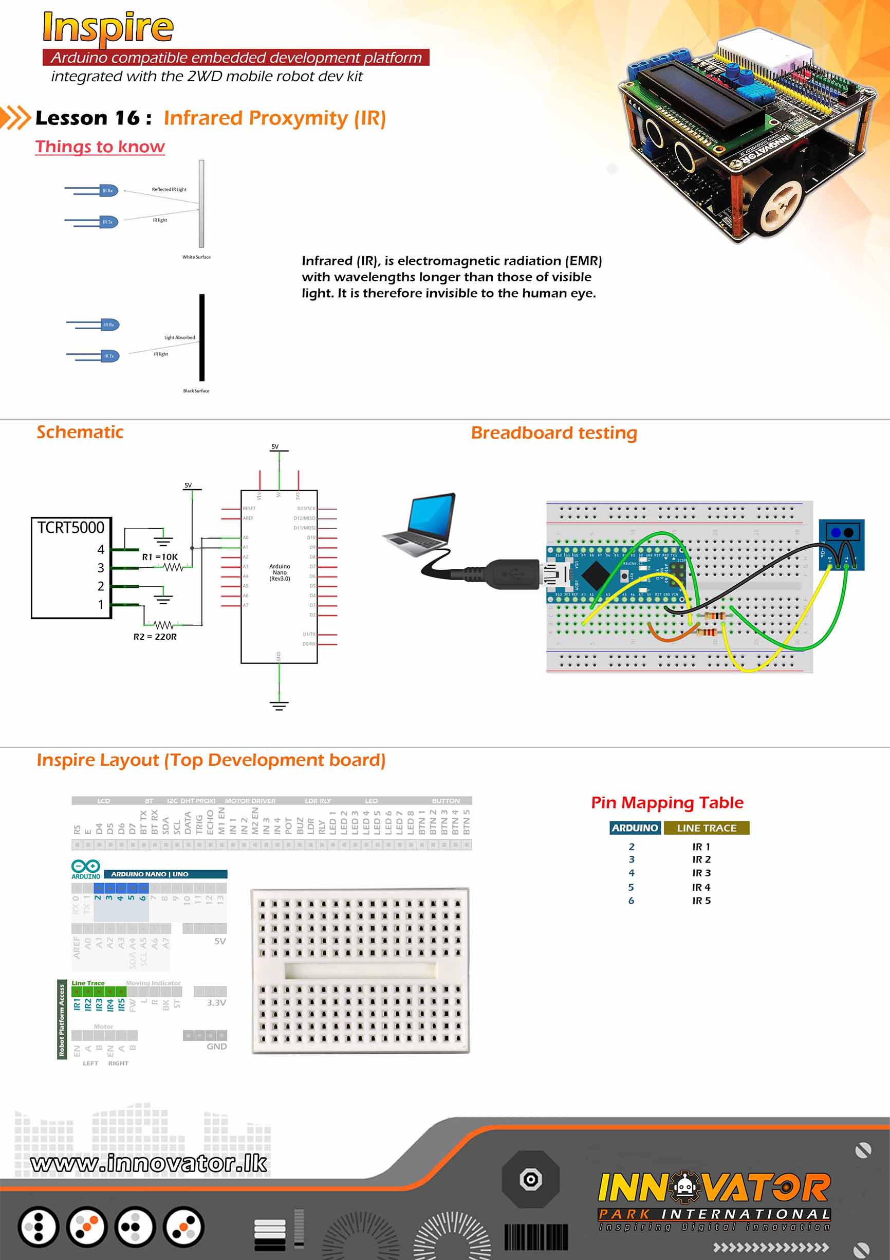
TRCT5000 IR Sensor(Line Following Sensors) Example.
------------------------------------------------------------------
Hardware setup :
plug a Arduino nano board in to the inspre top development board.
turn on power switch of the both top & bottom development boards.
Connect Line Tracing IR1 PIN to Arduino Digital PIN-> 2(D2)
Connect Line Tracing IR2 PIN to Arduino Digital PIN-> 3(D3)
Connect Line Tracing IR3 PIN to Arduino Digital PIN-> 4(D4)
Connect Line Tracing IR4 PIN to Arduino Digital PIN-> 5(D5)
Connect Line Tracing IR5 PIN to Arduino Digital PIN-> 6(D6)
-----------------------------------------------------------------
22 march 2021
*/
int IR1 = 2;// the number of the IR1 pin.
int IR2 = 3;// the number of the IR2 pin.
int IR3 = 4;// the number of the IR3 pin.
int IR4 = 5;// the number of the IR4 pin.
int IR5 = 6;// the number of the IR5 pin.
int s1, s2, s3, s4, s5; //creating five variables to hold the states of IR sensors.
void setup() {
pinMode(IR1, INPUT);//initializing IR1 pin as a input pin.
pinMode(IR2, INPUT);//initializing IR2 pin as a input pin.
pinMode(IR3, INPUT);//initializing IR3 pin as a input pin.
pinMode(IR4, INPUT);//initializing IR4 pin as a input pin.
pinMode(IR5, INPUT);//initializing IR5 pin as a input pin.
Serial.begin(9600);//starting serial communication between arduino and computer.
}
void loop() {
s1 = digitalRead(IR1);//reading and storing the state of IR1 to s1 variable
Serial.print(s1);//printing the value of "s1" variable to serial monitor.
Serial.print("t");//printing a tab character to serial monitor.
s2 = digitalRead(IR2);//reading and storing the state of IR2 to s2 variable
Serial.print(s2);//printing the value of "s2" variable to serial monitor.
Serial.print("t");//printing a tab character to serial monitor.
s3 = digitalRead(IR3);//reading and storing the state of IR3 to s3 variable
Serial.print(s3);//printing the value of "s3" variable to serial monitor.
Serial.print("t");//printing a tab character to serial monitor.
s4 = digitalRead(IR4);//reading and storing the state of IR4 to s4 variable
Serial.print(s4);//printing the value of "s4" variable to serial monitor.
Serial.print("t");//printing a tab character to serial monitor.
s5 = digitalRead(IR5);//reading and storing the state of IR5 to s5 variable
Serial.print(s5);//printing the value of "s5" variable to serial monitor.
Serial.print("t");//printing a tab character to serial monitor.
Serial.println("end");//printing a line end with a string.
}
/*
INNOVATOR INTERNATIONAL (PVT)LTD.
https://www.innovator.lk/
---------------------------------------------------------------------------
Development Platform : Inspire 1.0
(Arduino development platform)
---------------------------------------------------------------------------
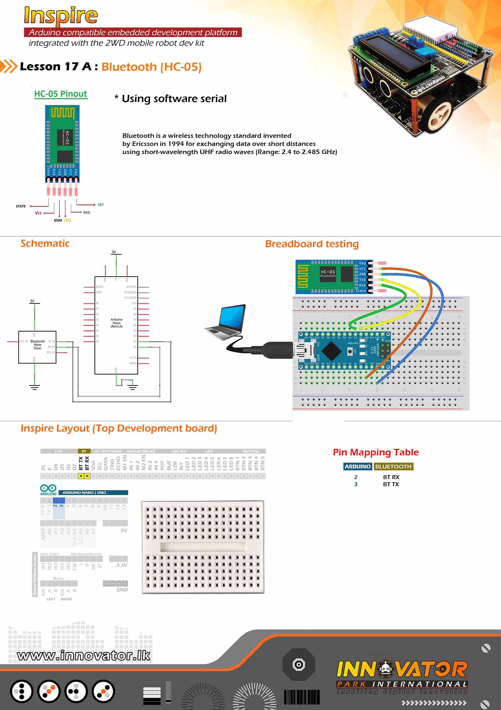
Bluetooth Receive Data Example.
---------------------------------------------------------------------------
Hardware setup :
plug a Arduino nano board in to the inspre top development board.
connect BLE RX PIN to Arduino Digital PIN-> 2(D2)
connect BLE TX PIN to Arduino Digital PIN-> 3(D3)
---------------------------------------------------------------------------
//Android Application :
//https://play.google.com/store/apps/details?id=project.bluetoothterminal
---------------------------------------------------------------------------
23 march 2021
*/
#include "SoftwareSerial.h"//including the software serial library.
SoftwareSerial btm(3, 2);//initiating software serial object.
char c;//a variable to hold the character received by the serial data.
void setup() {
btm.begin(9600);//starting software serial communication.
Serial.begin(9600);//starting serial communication between arduino and computer.
}
void loop() {
if (btm.available() > 0) {//check if software serial is containing any data.
while (btm.available() > 0) {//while there is data,
c = btm.read();//read it and store it in the variable called "c".
Serial.print(c);//printing stored variable to the serial monitor.
}
}
}
/*
  INNOVATOR INTERNATIONAL (PVT)LTD.
  https://www.innovator.lk/
  --------------------------------------------------------------------------
  Development Platform : Inspire 1.0
  (Arduino development platform)
  --------------------------------------------------------------------------
  Bluetooth Data Sending Example.
  --------------------------------------------------------------------------
  Hardware setup :
  plug a Arduino nano board in to the inspre top development board.

  connect BLE RX PIN to Arduino Digital PIN-> 2(D2)
  connect BLE TX PIN to Arduino Digital PIN-> 3(D3)
  ---------------------------------------------------------------------------
  //Android Application :
  //https://play.google.com/store/apps/details?id=project.bluetoothterminal
  ---------------------------------------------------------------------------
  23 march 2021
*/

#include "SoftwareSerial.h"//including the software serial library.

SoftwareSerial btm(3, 2);//initiating software serial object.

void setup() {
  btm.begin(9600);//starting software serial communication.
}

void loop() {
  btm.println("this is from inspire :) ");//printing a message to software serial.

  delay(1000);//keep a one second delay between each serial print.
}
/*
INNOVATOR INTERNATIONAL (PVT)LTD.
https://www.innovator.lk/
--------------------------------------------------------------------------
Development Platform : Inspire 1.0
(Arduino development platform)
--------------------------------------------------------------------------
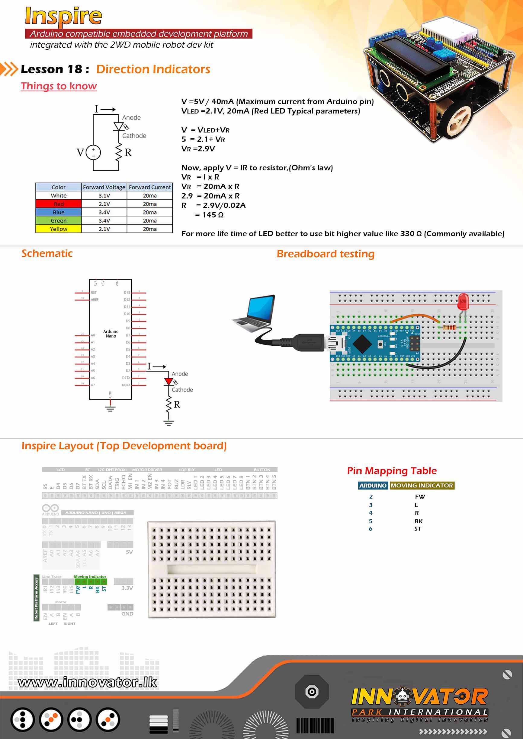
Direction Indicators Example (TOP Board).
--------------------------------------------------------------------------
Hardware setup :
plug in a Arduino nano board to the inspire top
develepment board.
--------------------------------------------------------------------------
Connect "Move Indicators" PIN FW(FORWARD) to arduino digital PIN 2(D2)
Connect "Move Indicators" PIN L (LEFT) to arduino digital PIN 3(D3)
Connect "Move Indicators" PIN R (RIGHT) to arduino digital PIN 4(D4)
Connect "Move Indicators" PIN BK(BACK) to arduino digital PIN 5(D5)
Connect "Move Indicators" PIN ST(STOP) to arduino digital PIN 6(D6)
--------------------------------------------------------------------------
22 march 2021
*/
byte LED_FORWARD = 2;//the number of the Arduino digital PIN,that FW PIN connected to.
byte LED_LEFT = 3;//the number of the Arduino digital PIN,that L PIN connected to.
byte LED_RIGHT = 4;//the number of the Arduino digital PIN,that R PIN connected to.
byte LED_BACK = 5;//the number of the Arduino digital PIN,that BK PIN connected to.
byte LED_STOP = 6;//the number of the Arduino digital PIN,that ST PIN connected to.
boolean FW, BK, ST, L, R, count;
void setup() {
//initializing all LED PINs as output PINs.
pinMode(LED_FORWARD, OUTPUT);
pinMode(LED_LEFT, OUTPUT);
pinMode(LED_RIGHT, OUTPUT);
pinMode(LED_BACK, OUTPUT);
pinMode(LED_STOP, OUTPUT);
//turning all LEDs off at the begining.
digitalWrite(LED_FORWARD, LOW);
digitalWrite(LED_LEFT, LOW);
digitalWrite(LED_RIGHT, LOW);
digitalWrite(LED_BACK, LOW);
digitalWrite(LED_STOP, LOW);
}
void loop() {
for (int i = 0; i <= 10; i++) {
forwardIndicator();
}
for (int i = 0; i <= 10; i++) {
stopIndicator();
}
for (int i = 0; i <= 10; i++) {
backwardIndicator();
}
for (int i = 0; i <= 10; i++) {
leftIndicator();
}
for (int i = 0; i <= 10; i++) {
rightIndicator();
}
}
void leftIndicator() {
digitalWrite(LED_LEFT, HIGH);
digitalWrite(LED_RIGHT, LOW);
delay(500);
digitalWrite(LED_LEFT, LOW);
delay(500);
}
void rightIndicator() {
digitalWrite(LED_RIGHT, HIGH);
digitalWrite(LED_LEFT, LOW);
delay(500);
digitalWrite(LED_RIGHT, LOW);
delay(500);
}
void forwardIndicator() {
digitalWrite(LED_FORWARD, HIGH);
digitalWrite(LED_STOP, LOW);
delay(500);
digitalWrite(LED_FORWARD, LOW);
delay(500);
}
void stopIndicator() {
digitalWrite(LED_STOP, HIGH);
digitalWrite(LED_FORWARD, LOW);
delay(500);
digitalWrite(LED_STOP, LOW);
delay(500);
}
void backwardIndicator() {
digitalWrite(LED_BACK, HIGH);
digitalWrite(LED_FORWARD, LOW);
delay(500);
digitalWrite(LED_BACK, LOW);
delay(500);
}
/*
INNOVATOR INTERNATIONAL (PVT)LTD.
https://www.innovator.lk/
------------------------------------------------------------------------------
Development Platform : Inspire 1.0
(Arduino development platform)
------------------------------------------------------------------------------
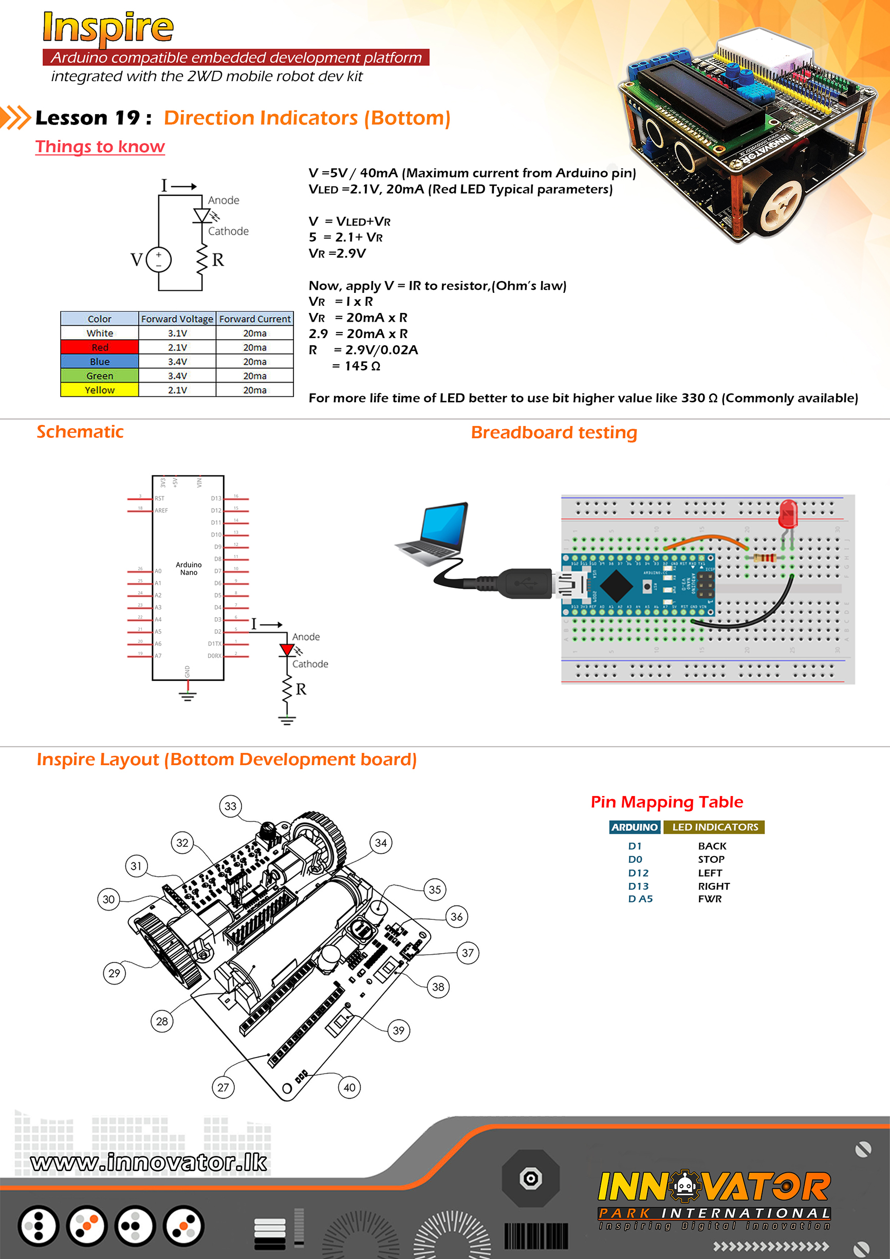
Direction Indicators Example (BOTTOM Board).
------------------------------------------------------------------------------
Hardware setup :
plug in a Arduino nano board to the inspire bottom
develepment board.
------------------------------------------------------------------------------
Connections to the indicators allready maped and
Connected as follows:
LED_FORWARD ->(LED:D9 AND LED:D16) connected to arduino analog PIN 5(A5)
LED_LEFT ->(LED:D10) connected to arduino digital PIN 12(D12)
LED_RIGHT ->(LED:D11) connected to arduino digital PIN 13(D13)
LED_BACK ->(LED:D13 AND LED:D15)connected to arduino digital PIN 1(D1)
LED_STOP ->(LED:D12 AND LED:D14) connected to arduino digital PIN 0(D0)
------------------------------------------------------------------------------
if you want to control direction indicators with top development platform
use "Move Indicators" PINs.
------------------------------------------------------------------------------
22 march 2021
*/
byte LED_FORWARD = A5;
byte LED_LEFT = 12;
byte LED_RIGHT = 13;
byte LED_BACK = 1;
byte LED_STOP = 0;
boolean FW, BK, ST, L, R, count;
void setup() {
//initializing all LED PINs as output PINs.
pinMode(LED_FORWARD, OUTPUT);
pinMode(LED_LEFT, OUTPUT);
pinMode(LED_RIGHT, OUTPUT);
pinMode(LED_BACK, OUTPUT);
pinMode(LED_STOP, OUTPUT);
//turning all LEDs off at the begining.
digitalWrite(LED_FORWARD, LOW);
digitalWrite(LED_LEFT, LOW);
digitalWrite(LED_RIGHT, LOW);
digitalWrite(LED_BACK, LOW);
digitalWrite(LED_STOP, LOW);
}
void loop() {
for (int i = 0; i <= 10; i++) {
forwardIndicator();
}
for (int i = 0; i <= 10; i++) {
stopIndicator();
}
for (int i = 0; i <= 10; i++) {
backwardIndicator();
}
for (int i = 0; i <= 10; i++) {
leftIndicator();
}
for (int i = 0; i <= 10; i++) {
rightIndicator();
}
}
void leftIndicator() {
digitalWrite(LED_LEFT, HIGH);
digitalWrite(LED_RIGHT, LOW);
delay(500);
digitalWrite(LED_LEFT, LOW);
delay(500);
}
void rightIndicator() {
digitalWrite(LED_RIGHT, HIGH);
digitalWrite(LED_LEFT, LOW);
delay(500);
digitalWrite(LED_RIGHT, LOW);
delay(500);
}
void forwardIndicator() {
digitalWrite(LED_FORWARD, HIGH);
digitalWrite(LED_STOP, LOW);
delay(500);
digitalWrite(LED_FORWARD, LOW);
delay(500);
}
void stopIndicator() {
digitalWrite(LED_STOP, HIGH);
digitalWrite(LED_FORWARD, LOW);
delay(500);
digitalWrite(LED_STOP, LOW);
delay(500);
}
void backwardIndicator() {
digitalWrite(LED_BACK, HIGH);
digitalWrite(LED_FORWARD, LOW);
delay(500);
digitalWrite(LED_BACK, LOW);
delay(500);
}
/*
  INNOVATOR INTERNATIONAL (PVT)LTD.
  https://www.innovator.lk/
  ------------------------------------------------------------------
  Development Platform : Inspire 1.0
  (Arduino development platform)
  ------------------------------------------------------------------
  hc-sr04 Ultrasonic Distance Sensor Example.
  ------------------------------------------------------------------
  Hardware setup :
  plug a Arduino nano board in to the inspre top development board.
  turn on power switch of the top development board.

  connect ECHO PIN to Arduino Digital PIN-> 11(D11)
  connect TRIG PIN to Arduino Digital PIN-> 10(D10)
  ------------------------------------------------------------------
  22 march 2021
*/

int ECHO = 11;// the number of the ECHO pin.

int TRIG = 10;// the number of the TRIG pin.


long duration; //a variable to hold the duration of sound wave travel value.

int distance; //a variable to hold the distance measurement value.

void setup() {
  pinMode(TRIG, OUTPUT); //initializing TRIG pin as a output pin.

  pinMode(ECHO, INPUT); //initializing ECHO pin as a input pin.

  Serial.begin(9600); //starting serial communication between arduino and computer.
}
void loop() {
  // making the TRIG pin LOW for 2 microseconds.
  digitalWrite(TRIG, LOW);
  delayMicroseconds(2);

  // making the TRIG pin HIGH for 10 microseconds.
  digitalWrite(TRIG, HIGH);
  delayMicroseconds(10);
  digitalWrite(TRIG, LOW);

  // reads the ECHO pin value and returns the sound wave travel time in microseconds.
  duration = pulseIn(ECHO, HIGH);
  // calculating the distance.
  distance = duration * 0.034 / 2; //speed of sound wave divided by 2 (to go forward and reflect on something and come back).

  // displays the calculated distance in the serial monitor.
  Serial.print("Distance: ");
  Serial.print(distance);
  Serial.println(" cm");
}
/*
  INNOVATOR INTERNATIONAL (PVT)LTD.
  https://www.innovator.lk/
  ------------------------------------------------------------------
  Development Platform : Inspire 1.0
  (Arduino development platform)
  ------------------------------------------------------------------
  TRCT5000 IR Sensor(Line Following Sensors) Example.
  ------------------------------------------------------------------
  Hardware setup :
  plug a Arduino nano board in to the inspre top development board.
  turn on power switch of the both top & bottom development boards.

  Connect Line Tracing IR1 PIN to Arduino Analog PIN-> 4(A4)

  Connect Line Tracing IR2 PIN to Arduino Analog PIN-> 3(A3)

  Connect Line Tracing IR3 PIN to Arduino Analog PIN-> 2(A2)

  Connect Line Tracing IR4 PIN to Arduino Analog PIN-> 1(A1)

  Connect Line Tracing IR5 PIN to Arduino Analog PIN-> 0(A0)
  -----------------------------------------------------------------
  22 march 2021
*/

int IR1 = A4;// the number of the IR1 pin.
int IR2 = A3;// the number of the IR2 pin.
int IR3 = A2;// the number of the IR3 pin.
int IR4 = A1;// the number of the IR4 pin.
int IR5 = A0;// the number of the IR5 pin.

int s1, s2, s3, s4, s5; //creating five variables to hold the states of IR sensors.

void setup() {
  pinMode(IR1, INPUT);//initializing IR1 pin as a input pin.
  pinMode(IR2, INPUT);//initializing IR2 pin as a input pin.
  pinMode(IR3, INPUT);//initializing IR3 pin as a input pin.
  pinMode(IR4, INPUT);//initializing IR4 pin as a input pin.
  pinMode(IR5, INPUT);//initializing IR5 pin as a input pin.

  Serial.begin(9600);//starting serial communication between arduino and computer.
}

void loop() {
  s1 = digitalRead(IR1);//reading and storing the state of IR1 to s1 variable
  Serial.print(s1);//printing the value of "s1" variable to serial monitor.
  Serial.print("t");//printing a tab character to serial monitor.


  s2 = digitalRead(IR2);//reading and storing the state of IR2 to s2 variable
  Serial.print(s2);//printing the value of "s2" variable to serial monitor.
  Serial.print("t");//printing a tab character to serial monitor.

  s3 = digitalRead(IR3);//reading and storing the state of IR3 to s3 variable
  Serial.print(s3);//printing the value of "s3" variable to serial monitor.
  Serial.print("t");//printing a tab character to serial monitor.

  s4 = digitalRead(IR4);//reading and storing the state of IR4 to s4 variable
  Serial.print(s4);//printing the value of "s4" variable to serial monitor.
  Serial.print("t");//printing a tab character to serial monitor.

  s5 = digitalRead(IR5);//reading and storing the state of IR5 to s5 variable
  Serial.print(s5);//printing the value of "s5" variable to serial monitor.
  Serial.print("t");//printing a tab character to serial monitor.

  Serial.println("end");//printing a line end with a string.
}
/*
  INNOVATOR INTERNATIONAL (PVT)LTD.
  https://www.innovator.lk/
  ---------------------------------------------------------------------------
  Development Platform : Inspire 1.0
  (Arduino development platform)
  ---------------------------------------------------------------------------
  Bluetooth Receive Data Example.
  ---------------------------------------------------------------------------
  Hardware setup :
  plug a Arduino nano board in to the inspre top development board.

  connect BLE RX PIN to Arduino Digital PIN-> 2(D2)
  connect BLE TX PIN to Arduino Digital PIN-> 3(D3)
  ---------------------------------------------------------------------------
  //Android Application :
  //https://play.google.com/store/apps/details?id=project.bluetoothterminal
  ---------------------------------------------------------------------------
  23 march 2021
*/

#include //including the software serial library.
SoftwareSerial btm(3, 2);//initiating software serial object.

char c;//a variable to hold the character received by the serial data.

void setup() {
  btm.begin(9600);//starting software serial communication.
  Serial.begin(9600);//starting serial communication between arduino and computer.
}

void loop() {
  if (btm.available() > 0) {//check if software serial is containing any data.

    while (btm.available() > 0) {//while there is data,
      c = btm.read();//read it and store it in the variable called "c".
      Serial.print(c);//printing stored variable to the serial monitor.
    }
  }
}
/*
  INNOVATOR INTERNATIONAL (PVT)LTD.
  https://www.innovator.lk/
  --------------------------------------------------------------------------
  Development Platform : Inspire 1.0
  (Arduino development platform)
  --------------------------------------------------------------------------
  Bluetooth Data Sending Example.
  --------------------------------------------------------------------------
  Hardware setup :
  plug a Arduino nano board in to the inspre top development board.

  connect BLE RX PIN to Arduino Digital PIN-> 2(D2)
  connect BLE TX PIN to Arduino Digital PIN-> 3(D3)
  ---------------------------------------------------------------------------
  //Android Application :
  //https://play.google.com/store/apps/details?id=project.bluetoothterminal
  ---------------------------------------------------------------------------
  23 march 2021
*/

#include //including the software serial library.

SoftwareSerial btm(3, 2);//initiating software serial object.

void setup() {
  btm.begin(9600);//starting software serial communication.
}

void loop() {
  btm.println("this is from inspire :) ");//printing a message to software serial.
  delay(1000);//keep a one second delay between each serial print.
}/*
INNOVATOR INTERNATIONAL (PVT)LTD.
https://www.innovator.lk/
------------------------------------------------------------------
Development Platform : Inspire 1.0
(Arduino development platform)
------------------------------------------------------------------
UP DOWN COUNTER WITH RESET .
------------------------------------------------------------------
Hardware setup :
plug a Arduino nano board in to the inspre top development board.
turn on power switch of the top development board.
Connect Arduino analog PIN 4(A4) to SDA
Connect Arduino analog PIN 4(A4) to SCL
------------------------------------------------------------------
connect Arduino digital PIN 2 to BTN 1
connect Arduino digital PIN 3 to BTN 2
connect Arduino digital PIN 4 to BTN 3
------------------------------------------------------------------
3 may 2021
*/
#include "LiquidCrystal_I2C.h"
int BUTTON_UP = 2;
int BUTTON_DOWN = 3;
int BUTTON_RESET = 4;
int COUNTER = 0;
LiquidCrystal_I2C lcd(0x27, 16, 2);
void setup()
{
lcd.begin();
pinMode(BUTTON_UP, INPUT);
pinMode(BUTTON_DOWN, INPUT);
lcd.setCursor(0, 0);
lcd.print("Up Down Counter");
delay(1000);
lcd.clear();
lcd.setCursor(0, 0);
lcd.print("Counter : ");
}
void loop() {
if (!digitalRead(BUTTON_UP)) {
COUNTER++;
lcd.clear();
lcd.setCursor(0, 0);
lcd.print("Counter : ");
lcd.setCursor(10, 0);
lcd.print(COUNTER);
delay(300);
} else if (!digitalRead(BUTTON_DOWN)) {
if (COUNTER > 0) {
COUNTER--;
lcd.clear();
lcd.setCursor(0, 0);
lcd.print("Counter : ");
lcd.setCursor(10, 0);
lcd.print(COUNTER);
delay(300);
}
} else if (!digitalRead(BUTTON_RESET)) {
COUNTER = 0;
lcd.clear();
lcd.setCursor(0, 0);
lcd.print("Counter : ");
lcd.setCursor(10, 0);
lcd.print(COUNTER);
delay(300);
}
}/*
INNOVATOR INTERNATIONAL (PVT)LTD.
https://www.innovator.lk/
------------------------------------------------------------------
Development Platform : Inspire 1.0
(Arduino development platform)
------------------------------------------------------------------
RANDOM NUMBER GENERATOR WITH MIN MAX .
------------------------------------------------------------------
Hardware setup :
plug a Arduino nano board in to the inspre top development board.
turn on power switch of the top development board.
connect Arduino analog PIN 4(A4) to SDA
connect Arduino analog PIN 4(A4) to SCL
------------------------------------------------------------------
connect Arduino digital PIN 2 to BTN 1
connect Arduino analog PIN A0 to POT
------------------------------------------------------------------
3 may 2021
*/
#include "LiquidCrystal_I2C.h"
int BUTTON = 2;
int NUMBER = 0;
int POT = A0;
int SEED = 0;
int MIN_NUMBER = 0;
int MAX_NUMBER = 5000;
LiquidCrystal_I2C lcd(0x27, 16, 2);
void setup() {
lcd.begin();
pinMode(BUTTON, INPUT);
pinMode(POT, INPUT);
lcd.setCursor(0, 0);
lcd.print("Random Number");
lcd.setCursor(0, 1);
lcd.print(" Generator");
delay(1000);
lcd.clear();
lcd.setCursor(0, 0);
lcd.print("Number : ");
}
void loop() {
SEED = analogRead(POT);
if (!digitalRead(BUTTON)) {
randomSeed(SEED);
NUMBER = random(MIN_NUMBER, MAX_NUMBER);
lcd.clear();
lcd.setCursor(0, 0);
lcd.print("Number : ");
lcd.setCursor(9, 0);
lcd.print(NUMBER);
delay(300);
}
}/*
INNOVATOR INTERNATIONAL (PVT)LTD.
https://www.innovator.lk/
------------------------------------------------------------------
Development Platform : Inspire 1.0
(Arduino development platform)
------------------------------------------------------------------
PASSWORD GENERATOR .
------------------------------------------------------------------
Hardware setup :
plug a Arduino nano board in to the inspre top development board.
turn on power switch of the top development board.
Connect Arduino analog PIN 4(A4) to SDA
Connect Arduino analog PIN 4(A4) to SCL
------------------------------------------------------------------
connect Arduino digital PIN 2 to BTN 1
connect Arduino analog PIN A0 to POT
------------------------------------------------------------------
3 may 2021
*/
#include "LiquidCrystal_I2C.h"
int BUTTON = 2;
int POT = A0;
char ENTRY;
char ARRAY[14] = {'1', '2', '3', '4', '5', '6', '7', '8', '9', '0', 'A', 'B', 'C', 'D'};
int SEED = 0;
int PASSWORD_LENGTH = 8;
LiquidCrystal_I2C lcd(0x27, 16, 2);
void setup() {
lcd.begin();
pinMode(BUTTON, INPUT);
pinMode(POT, INPUT);
lcd.setCursor(0, 0);
lcd.print("Password");
lcd.setCursor(0, 1);
lcd.print("Generator");
delay(1000);
lcd.clear();
lcd.setCursor(0, 0);
lcd.print("Password : ");
}
void loop() {
SEED = analogRead(POT);
randomSeed(SEED);
if (!digitalRead(BUTTON)) {
for (int i = 0; i < PASSWORD_LENGTH; i++) {
ENTRY = ARRAY[rand() % 14];
lcd.setCursor(i, 1);
lcd.print( ENTRY);
}
delay(300);
}
}/*
INNOVATOR INTERNATIONAL (PVT)LTD.
https://www.innovator.lk/
------------------------------------------------------------------
Development Platform : Inspire 1.0
(Arduino development platform)
------------------------------------------------------------------
VARIABLE TONE GENERATOR 20HZ - 2000HZ .
------------------------------------------------------------------
Hardware setup :
plug a Arduino nano board in to the inspre top development board.
turn on power switch of the top development board.
Connect Arduino analog PIN 4(A4) to SDA
Connect Arduino analog PIN 4(A4) to SCL
------------------------------------------------------------------
connect Arduino digital PIN 7 to BUZ
connect Arduino analog PIN A0 to POT
------------------------------------------------------------------
3 may 2021
*/
#include "LiquidCrystal_I2C.h"
LiquidCrystal_I2C lcd(0x27, 16, 2);
int DELAY = 1000;
unsigned long TIME_NOW = 0;
int POT = A0;
int VALUE = 0;
int FREQUENCY = 0;
const int BUZZER = 7;
void playTone(int FREQUENCY) {
lcd.clear();
lcd.setCursor(0, 0);
lcd.print("Frequency :");
tone(BUZZER, FREQUENCY);
lcd.setCursor(0, 1);
lcd.print(FREQUENCY);
lcd.setCursor(5, 1);
lcd.print("Hz");
}
void setup() {
pinMode(BUZZER, OUTPUT);
lcd.begin();
lcd.setCursor(0, 0);
lcd.print("Tone Generator");
delay(1000);
}
void loop() {
TIME_NOW = millis();
VALUE = analogRead(POT);
FREQUENCY = ceil(VALUE / 5) * 5 * 2;
if (FREQUENCY > 2000) {
FREQUENCY = 2000;
}
if (FREQUENCY < 20) {
FREQUENCY = 20;
}
playTone(FREQUENCY);
while (millis() < TIME_NOW + DELAY) {
//wait for 1second and update LCD screen
}
}/*
INNOVATOR INTERNATIONAL (PVT)LTD.
https://www.innovator.lk/
------------------------------------------------------------------
Development Platform : Inspire 1.0
(Arduino development platform)
------------------------------------------------------------------
8 LED LARSON SCANNER .
------------------------------------------------------------------
Hardware setup :
plug a Arduino nano board in to the inspre top development board.
turn on power switch of the top development board.
connect Arduino analog PIN 4(A4) to SDA
connect Arduino analog PIN 4(A4) to SCL
------------------------------------------------------------------
connect Arduino digital PIN 2 to LED 1
connect Arduino digital PIN 3 to LED 2
connect Arduino digital PIN 4 to LED 3
connect Arduino digital PIN 5 to LED 4
connect Arduino digital PIN 6 to LED 5
connect Arduino digital PIN 7 to LED 6
connect Arduino digital PIN 8 to LED 7
connect Arduino digital PIN 9 to LED 8
------------------------------------------------------------------
3 may 2021
*/
#include "LiquidCrystal_I2C.h"
LiquidCrystal_I2C lcd(0x27, 16, 2);
int DELAY = 80;
void setup() {
for (int i = 2; i < 10; i++) {
pinMode(i, OUTPUT);
}
for (int i = 2; i < 10; i++) {
digitalWrite(i, LOW);
}
lcd.begin();
lcd.setCursor(0, 0);
lcd.print("larson scanner");
delay(1000);
}
void loop() {
larson_scanner();
}
void larson_scanner() {
for (int i = 2; i <= 10; i++) { digitalWrite(i, HIGH); delay(DELAY); digitalWrite(i, LOW); } for (int i = 9; i >= 3; i--) {
digitalWrite(i, HIGH);
delay(DELAY);
digitalWrite(i, LOW);
}
}/*
INNOVATOR INTERNATIONAL (PVT)LTD.
https://www.innovator.lk/
------------------------------------------------------------------
Development Platform : Inspire 1.0
(Arduino development platform)
------------------------------------------------------------------
DIGITAL DICE .
------------------------------------------------------------------
Hardware setup :
plug a Arduino nano board in to the inspre top development board.
turn on power switch of the top development board.
connect Arduino analog PIN 4(A4) to SDA
connect Arduino analog PIN 4(A4) to SCL
------------------------------------------------------------------
connect Arduino digital PIN 2 to LED 1
connect Arduino digital PIN 3 to LED 2
connect Arduino digital PIN 4 to LED 3
connect Arduino digital PIN 5 to LED 4
connect Arduino digital PIN 6 to LED 5
connect Arduino digital PIN 7 to LED 6
connect Arduino digital PIN 8 to BTN 1
------------------------------------------------------------------
3 may 2021
*/
#include "LiquidCrystal_I2C.h"
LiquidCrystal_I2C lcd(0x27, 16, 2);
int BUTTON = 8;
int NUMBER = 0;
void setup() {
for (int i = 2; i < 8; i++) {
pinMode(i, OUTPUT);
}
pinMode(BUTTON, INPUT);
for (int i = 2; i < 8; i++) {
digitalWrite(i, LOW);
}
lcd.begin();
lcd.setCursor(0, 0);
lcd.print("digital dice");
delay(1000);
}
void loop() {
if (!digitalRead(BUTTON)) {
NUMBER = random(1, 7);
lcd.setCursor(0, 1);
lcd.print("dice value : ");
lcd.setCursor(13, 1);
lcd.print(NUMBER);
for (int i = 2; i < 8; i++) {
digitalWrite(i, LOW);
}
if (NUMBER == 1) {
digitalWrite(2, HIGH);
}
if (NUMBER == 2) {
digitalWrite(3, HIGH);
}
if (NUMBER == 3) {
digitalWrite(4, HIGH);
}
if (NUMBER == 4) {
digitalWrite(5, HIGH);
}
if (NUMBER == 5) {
digitalWrite(6, HIGH);
}
if (NUMBER == 6) {
digitalWrite(7, HIGH);
}
delay(300);
}
}/*
INNOVATOR INTERNATIONAL (PVT)LTD.
https://www.innovator.lk/
------------------------------------------------------------------
Development Platform : Inspire 1.0
(Arduino development platform)
------------------------------------------------------------------
DIGITAL LOCK WITH PASSCODE.
------------------------------------------------------------------
Hardware setup :
plug a Arduino nano board in to the inspre top development board.
turn on power switch of the top development board.
connect Arduino analog PIN 4(A4) to SDA
connect Arduino analog PIN 4(A4) to SCL
------------------------------------------------------------------
connect Arduino digital PIN 2 to LED 4
connect Arduino digital PIN 3 to LED 5
connect Arduino digital PIN 4 to RLY
connect Arduino digital PIN 5 to BTN 1
connect Arduino digital PIN 6 to BTN 2
connect Arduino analog PIN A0 to POT
------------------------------------------------------------------
3 may 2021
*/
#include "LiquidCrystal_I2C.h"
LiquidCrystal_I2C lcd(0x27, 16, 2);
int LOCK_LED = 2;
int NOT_LOCK_LED = 3;
int RELAY = 4;
int UNLOCK_BUTTON = 5;
int LOCK_BUTTON = 6;
int POT = A0;
int NUMBER_1 = 0;
int VALUE = 0;
int CODE = 52;
void setup() {
pinMode(UNLOCK_BUTTON, INPUT);
pinMode(LOCK_BUTTON, INPUT);
pinMode(POT, INPUT);
pinMode(RELAY, OUTPUT);
pinMode(LOCK_LED, OUTPUT);
pinMode(NOT_LOCK_LED, OUTPUT);
digitalWrite(RELAY, HIGH);
digitalWrite(LOCK_LED, HIGH);
lcd.begin();
lcd.setCursor(0, 0);
lcd.print("digital lock");
delay(1000);
}
void loop() {
VALUE = analogRead(POT);
VALUE = map(VALUE, 0, 1023, 0, 255);
delay(200);
lcd.setCursor(0, 1);
lcd.print("Enter code :");
lcd.setCursor(13, 1);
lcd.print(VALUE);
if (!digitalRead(UNLOCK_BUTTON)) {
NUMBER_1 = VALUE;
}
if (NUMBER_1 == CODE) {
digitalWrite(LOCK_LED, LOW);
digitalWrite(NOT_LOCK_LED, HIGH);
digitalWrite(RELAY, LOW);
}
if (!digitalRead(LOCK_BUTTON)) {
NUMBER_1 = 0;
digitalWrite(LOCK_LED, HIGH);
digitalWrite(NOT_LOCK_LED, LOW);
digitalWrite(RELAY, HIGH);
}
}/*
INNOVATOR INTERNATIONAL (PVT)LTD.
https://www.innovator.lk/
------------------------------------------------------------------
Development Platform : Inspire 1.0
(Arduino development platform)
------------------------------------------------------------------
DIGITAL LOCK WITH PASSCODE.
------------------------------------------------------------------
Hardware setup :
plug a Arduino nano board in to the inspre top development board.
turn on power switch of the top development board.
connect Arduino analog PIN 4(A4) to SDA
connect Arduino analog PIN 4(A4) to SCL
------------------------------------------------------------------
connect Arduino digital PIN 9 to TRIG PIN
connect Arduino digital PIN 10 to ECHO PIN
connect Arduino digital PIN 3 to BUZ PIN
------------------------------------------------------------------
4 may 2021
*/
#include "LiquidCrystal_I2C.h"
LiquidCrystal_I2C lcd(0x27, 16, 2);
int TRIGGER_PIN = 9;
int ECHO_PIN = 10;
int BUZZER = 3;
long DURATION;
int DISTANCE;
long FIRST_OFF;
int DISTANCE_FIRST;
void setup()
{
lcd.begin();
lcd.setCursor(0, 0);
lcd.print("Trip Wire");
delay(1000);
pinMode(TRIGGER_PIN, OUTPUT);
pinMode(ECHO_PIN, INPUT);
digitalWrite(TRIGGER_PIN, HIGH);
delayMicroseconds(10);
digitalWrite(TRIGGER_PIN, LOW);
FIRST_OFF = pulseIn(ECHO_PIN, HIGH);
DISTANCE_FIRST = FIRST_OFF * 0.034 / 2;
}
void loop()
{
digitalWrite(TRIGGER_PIN, LOW);
delayMicroseconds(2);
digitalWrite(TRIGGER_PIN, HIGH);
delayMicroseconds(10);
digitalWrite(TRIGGER_PIN, LOW);
DURATION = pulseIn(ECHO_PIN, HIGH);
DISTANCE = DURATION * 0.034 / 2;
delay(300);
if (DISTANCE <= DISTANCE_FIRST - 5)
{
tone(BUZZER, 500, 500);
delay(500);
tone(BUZZER, 800, 500);
delay(500);
delay(50);
}
}/*
INNOVATOR INTERNATIONAL (PVT)LTD.
https://www.innovator.lk/
-------------------------------------------------------------------
Development Platform : Inspire 1.0
(Arduino development platform)
-------------------------------------------------------------------
SOFTWARE PWM.
-------------------------------------------------------------------
Hardware setup :
plug a Arduino nano board in to the inspre top development board.
turn on power switch of the top development board.
connect POT PIN to Arduino Analog PIN-> 0(A0)
connect LED1 PIN to Arduino Digital PIN-> 8(D8)
turn on power switch of the top development board.
-------------------------------------------------------------------
11 may 2021
*/
float FREQUENCY = 100;
float CYCLE_LENGTH;
float DUTY_CYCLE;
int ON_TIME;
int OFF_TIME;
float VOUT;
int POT = A0;
int LED = 8;
void setup() {
Serial.begin(9600);
pinMode(POT, INPUT);
pinMode(LED, OUTPUT);
digitalWrite(LED, LOW);
CYCLE_LENGTH = 1000000 / FREQUENCY;
}
void loop() {
int val = analogRead(POT);
VOUT = map(val, 0, 1024, 0, 255);
DUTY_CYCLE = VOUT / 255;
ON_TIME = DUTY_CYCLE * CYCLE_LENGTH;
OFF_TIME = CYCLE_LENGTH - ON_TIME;
if (ON_TIME > 0)
{
digitalWrite(LED, HIGH);
delayMicroseconds(ON_TIME);
}
digitalWrite(LED, LOW);
delayMicroseconds(OFF_TIME);
}/*
INNOVATOR INTERNATIONAL (PVT)LTD.
https://www.innovator.lk/
--------------------------------------------------------
Development Platform : Inspire 1.0
(Arduino development platform)
--------------------------------------------------------
LED PATTERNS.
--------------------------------------------------------
Hardware setup :
connect LED1 PIN to Arduino Digital PIN-> 2(D2)
connect LED2 PIN to Arduino Digital PIN-> 3(D3)
connect LED3 PIN to Arduino Digital PIN-> 4(D4)
connect LED4 PIN to Arduino Digital PIN-> 5(D5)
connect LED5 PIN to Arduino Digital PIN-> 6(D6)
connect LED6 PIN to Arduino Digital PIN-> 7(D7)
connect LED7 PIN to Arduino Digital PIN-> 8(D8)
connect LED8 PIN to Arduino Digital PIN-> 9(D9)
--------------------------------------------------------
11 may 2021
*/
void setup() {
Serial.begin(9600);
for (int i = 2 ; i < 10; i++ ) {
pinMode(i, OUTPUT);
}
for (int i = 2 ; i < 10; i++ ) {
digitalWrite(i, LOW);
}
}
void loop() {
for (int i = 0 ; i < 5; i++ ) {
pattern1();
}
for (int i = 0 ; i < 5; i++ ) {
pattern2();
}
for (int i = 0 ; i < 5; i++ ) {
pattern3();
}
for (int i = 0 ; i < 20; i++ ) {
pattern4();
}
for (int i = 0 ; i < 5; i++ ) {
pattern5();
}
for (int i = 0 ; i < 5; i++ ) {
pattern6();
}
for (int i = 0 ; i < 5; i++ ) {
pattern7();
}
for (int i = 0 ; i < 5; i++ ) {
pattern8();
}
for (int i = 0 ; i < 5; i++ ) {
pattern9();
}
for (int i = 0 ; i < 5; i++ ) {
pattern10();
}
}
void pattern1() {
for (int i = 2 ; i < 10; i++ ) {
digitalWrite(i, HIGH);
delay(200);
if (i == 9) {
for (int i = 2 ; i < 10; i++ ) {
digitalWrite(i, LOW);
}
delay(200);
}
}
}
void pattern2() {
for (int i = 2 ; i < 10; i++ ) {
digitalWrite(i, HIGH);
}
delay(200);
for (int i = 2 ; i < 10; i++ ) {
digitalWrite(i, LOW);
}
delay(200);
}
void pattern3() {
for (int i = 2 ; i < 6; i++ ) {
digitalWrite(i, HIGH);
}
delay(100);
for (int i = 2 ; i < 6; i++ ) {
digitalWrite(i, LOW);
}
delay(100);
for (int i = 6 ; i < 10; i++ ) {
digitalWrite(i, HIGH);
}
delay(100);
for (int i = 6 ; i < 10; i++ ) {
digitalWrite(i, LOW);
}
delay(100);
}
void pattern4() {
for (int i = 2 ; i < 10; i++ ) {
digitalWrite(i, LOW);
}
delay(100);
digitalWrite(random(2, 10), HIGH);
delay(100);
for (int i = 2 ; i < 10; i++ ) {
digitalWrite(i, LOW);
}
}
void pattern5() {
for (int i = 2 ; i < 6; i++ ) { digitalWrite(i, HIGH); delay(200); } for (int i = 10 ; i > 5; i-- ) {
digitalWrite(i, HIGH);
delay(200);
}
for (int i = 2 ; i < 10; i++ ) {
digitalWrite(i, LOW);
}
delay(200);
}
void pattern6() {
digitalWrite(2, HIGH);
digitalWrite(9, HIGH);
delay(100);
digitalWrite(3, HIGH);
digitalWrite(8, HIGH);
delay(100);
digitalWrite(4, HIGH);
digitalWrite(7, HIGH);
delay(100);
digitalWrite(5, HIGH);
digitalWrite(6, HIGH);
delay(100);
for (int i = 2 ; i < 10; i++ ) {
digitalWrite(i, LOW);
}
delay(100);
}
void pattern7() {
digitalWrite(2, HIGH);
digitalWrite(4, HIGH);
digitalWrite(6, HIGH);
digitalWrite(8, HIGH);
delay(100);
digitalWrite(2, LOW);
digitalWrite(4, LOW);
digitalWrite(6, LOW);
digitalWrite(8, LOW);
delay(100);
digitalWrite(3, HIGH);
digitalWrite(5, HIGH);
digitalWrite(7, HIGH);
digitalWrite(9, HIGH);
delay(100);
digitalWrite(3, LOW);
digitalWrite(5, LOW);
digitalWrite(7, LOW);
digitalWrite(9, LOW);
delay(100);
}
void pattern8() {
digitalWrite(2, HIGH);
digitalWrite(4, HIGH);
digitalWrite(6, HIGH);
digitalWrite(8, HIGH);
digitalWrite(3, LOW);
digitalWrite(5, LOW);
digitalWrite(7, LOW);
digitalWrite(9, LOW);
delay(500);
digitalWrite(3, HIGH);
digitalWrite(5, HIGH);
digitalWrite(7, HIGH);
digitalWrite(9, HIGH);
digitalWrite(2, LOW);
digitalWrite(4, LOW);
digitalWrite(6, LOW);
digitalWrite(8, LOW);
delay(500);
}
void pattern9() {
digitalWrite(5, HIGH);
digitalWrite(6, HIGH);
delay(100);
digitalWrite(4, HIGH);
digitalWrite(7, HIGH);
delay(100);
digitalWrite(3, HIGH);
digitalWrite(8, HIGH);
delay(100);
digitalWrite(2, HIGH);
digitalWrite(9, HIGH);
delay(100);
for (int i = 2 ; i < 10; i++ ) {
digitalWrite(i, LOW);
}
delay(100);
}
void pattern10() {
digitalWrite(2, HIGH);
digitalWrite(3, HIGH);
digitalWrite(4, HIGH);
digitalWrite(5, HIGH);
delay(30);
digitalWrite(2, LOW);
digitalWrite(3, LOW);
digitalWrite(4, LOW);
digitalWrite(5, LOW);
delay(30);
digitalWrite(6, HIGH);
digitalWrite(7, HIGH);
digitalWrite(8, HIGH);
digitalWrite(9, HIGH);
delay(20);
digitalWrite(6, LOW);
digitalWrite(7, LOW);
digitalWrite(8, LOW);
digitalWrite(9, LOW);
delay(20);
}/*
INNOVATOR INTERNATIONAL (PVT)LTD.
https://www.innovator.lk/
------------------------------------------------------------------
Development Platform : Inspire 1.0
(Arduino development platform)
------------------------------------------------------------------
DS1307 ALARM CLOCK.
------------------------------------------------------------------
Hardware setup :
plug a Arduino nano board in to the inspre top development board.
turn on power switch of the top development board.
connect Arduino analog PIN 4(A4) to SDA
connect Arduino analog PIN 4(A4) to SCL
connect Arduino digital PIN 11(D11) to BUZ
------------------------------------------------------------------
11 may 2021
*/
#include "Wire.h"
#include "RTClib.h"
#include "LiquidCrystal_I2C.h"
LiquidCrystal_I2C lcd(0x27, 16, 2);
RTC_DS1307 RTC;
const int BUZZER = 11;
char BUFFER [16];
int HOUR;
int MINUTE;
int SECOND;
int ALARM_HOUR = 10;
int ALARM_MINUTE = 41;
byte BELL_ICON[8] = {B00000, B00100, B01110, B01110, B01110, B11111, B00100, B00000};
void setup () {
Serial.begin(9600);
Wire.begin();
RTC.begin();
lcd.begin();
pinMode(BUZZER, OUTPUT);
if (! RTC.isrunning()) {
Serial.println("RTC is NOT running!");
RTC.adjust(DateTime(2021, 05, 11, 9, 56, 0));
}
lcd.createChar(0, BELL_ICON);
}
void loop () {
DateTime now = RTC.now();
LCDDate(now);
LCDTime(now);
if (now.hour() == ALARM_HOUR && now.minute() == ALARM_MINUTE ) {
lcd.setCursor(15, 1);
lcd.write(byte(0));
Buzz();
} else {
lcd.setCursor(15, 1);
lcd.print(" ");
}
}
void Buzz() {
tone(BUZZER, 1000);
delay(500);
noTone(BUZZER);
delay(500);
}
void LCDDate(DateTime NOW) {
lcd.setCursor(0, 0);
lcd.print(NOW.day(), DEC);
lcd.print('/');
lcd.print(NOW.month(), DEC);
lcd.print('/');
lcd.print(NOW.year(), DEC);
lcd.print(' ');
}
void LCDTime(DateTime NOW) {
HOUR = NOW.hour();
MINUTE = NOW.minute();
SECOND = NOW.second();
sprintf (BUFFER, "%02u:%02u:%02u", HOUR, MINUTE, SECOND);
lcd.setCursor(0, 1);
lcd.print(BUFFER);
}/*
INNOVATOR INTERNATIONAL (PVT)LTD.
https://www.innovator.lk/
-------------------------------------------------------------------
Development Platform : Inspire 1.0
(Arduino development platform)
-------------------------------------------------------------------
BREATHING LED.
-------------------------------------------------------------------
Hardware setup :
plug a Arduino nano board in to the inspre top development board.
turn on power switch of the top development board.
connect LED1 PIN to Arduino Digital PIN-> 3(D3)
turn on power switch of the top development board.
-------------------------------------------------------------------
11 may 2021
*/
int LED = 3;
void setup() {
pinMode(LED, OUTPUT);
}
void loop() {
fadeOn(1000, 5);
fadeOff(1000, 5);
}
void fadeOn(unsigned int time, int i) {
for (byte VALUE = 0 ; VALUE < 255; VALUE += i) { analogWrite(LED, VALUE); delay(time / (255 / 5)); } } void fadeOff(unsigned int time, int d) { for (byte VALUE = 255; VALUE > 0; VALUE -= d) {
analogWrite(LED, VALUE);
delay(time / (255 / 5));
}
}/*
INNOVATOR INTERNATIONAL (PVT)LTD.
https://www.innovator.lk/
----------------------------------------------------------------------
Development Platform : Inspire 1.0
(Arduino development platform)
----------------------------------------------------------------------
OBSTACLE AVOIDING ROBOT.
----------------------------------------------------------------------
Hardware setup :
plug a Arduino nano board in to the inspre top development board.
turn on both power switchs of the top development board & bottom one.
----------------------------------------------------------------------
connect LEFT_EN to Arduino Digital PIN-> 5(D5)
connect LEFT_A to Arduino Digital PIN-> 3(D4)
connect LEFT_B to Arduino Digital PIN-> 4(D3)
----------------------------------------------------------------------
connect RIGHT_EN to Arduino Analog PIN-> 6(D6)
connect RIGHT_A to Arduino Digital PIN-> 7(D7)
connect RIGHT_B to Arduino Digital PIN-> 8(D8)
----------------------------------------------------------------------
connect PROXI TRIG PIN to Arduino Digital PIN->9(D9)
connect ECHO TRIG PIN to Arduino Digital PIN->10(D10)
----------------------------------------------------------------------
11 may 2021
*/
int TRIGGER_PIN = 9;
int ECHO_PIN = 10;
int LEFT_EN = 5;
int LEFT_A = 4;
int LEFT_B = 3;
int RIGHT_EN = 6;
int RIGHT_A = 7;
int RIGHT_B = 8;
long DURATION, DISTANCE;
void setup() {
Serial.begin(9600);
pinMode(LEFT_EN, OUTPUT);
pinMode(RIGHT_EN, OUTPUT);
pinMode(LEFT_A, OUTPUT);
pinMode(LEFT_B, OUTPUT);
pinMode(RIGHT_A, OUTPUT);
pinMode(RIGHT_B, OUTPUT);
digitalWrite(LEFT_A, LOW);
digitalWrite(LEFT_B, LOW);
digitalWrite(RIGHT_A, LOW);
digitalWrite(RIGHT_B, LOW);
pinMode(TRIGGER_PIN, OUTPUT);
pinMode(ECHO_PIN, INPUT);
}
void loop() {
digitalWrite(TRIGGER_PIN, LOW);
delayMicroseconds(2);
digitalWrite(TRIGGER_PIN, HIGH);
delayMicroseconds(10);
DURATION = pulseIn(ECHO_PIN, HIGH);
DISTANCE = DURATION / 58.2;
delay(10);
if (DISTANCE > 19)
{
foward();
}
if (DISTANCE < 18)
{
stopAll();
delay(500);
backward();
delay(500);
stopAll();
delay(100);
left();
delay(500);
}
}
void foward() {
analogWrite(LEFT_EN, 255);
analogWrite(RIGHT_EN, 255);
digitalWrite(LEFT_A, HIGH);
digitalWrite(LEFT_B, LOW);
digitalWrite(RIGHT_A, LOW);
digitalWrite(RIGHT_B, HIGH);
}
void backward() {
analogWrite(LEFT_EN, 255);
analogWrite(RIGHT_EN, 255);
digitalWrite(LEFT_A, LOW);
digitalWrite(LEFT_B, HIGH);
digitalWrite(RIGHT_A, HIGH);
digitalWrite(RIGHT_B, LOW);
}
void stopAll() {
digitalWrite(LEFT_A, LOW);
digitalWrite(LEFT_B, LOW);
digitalWrite(RIGHT_A, LOW);
digitalWrite(RIGHT_B, LOW);
}
void left() {
analogWrite(LEFT_EN, 255);
analogWrite(RIGHT_EN, 255);
digitalWrite(LEFT_A, LOW);
digitalWrite(LEFT_B, HIGH);
digitalWrite(RIGHT_A, LOW);
digitalWrite(RIGHT_B, HIGH);
}
void right() {
analogWrite(LEFT_EN, 255);
analogWrite(RIGHT_EN, 255);
digitalWrite(LEFT_A, HIGH);
digitalWrite(LEFT_B, LOW);
digitalWrite(RIGHT_A, HIGH);
digitalWrite(RIGHT_B, LOW);
}/*
INNOVATOR INTERNATIONAL (PVT)LTD.
https://www.innovator.lk/
-------------------------------------------------------------------
Development Platform : Inspire 1.0
(Arduino development platform)
-------------------------------------------------------------------
BUTTON DEBOUNCE.
-------------------------------------------------------------------
Hardware setup :
plug a Arduino nano board in to the inspre top development board.
turn on power switch of the top development board.
connect LED1 to Arduino Digital PIN 2 (D2)
connect BTN1 to Arduino Digital PIN 3 (D3)
-------------------------------------------------------------------
01 june 2021
*/
int LED1 = 2;
int BUTTON1 = 3;
int LED_STATE = HIGH;
int BUTTON_STATE;
int BUTTON_STATE_PREVIOUS = LOW;
unsigned long PREVIOUS_DEBOUNCE_TIME = 0;
unsigned long DEBOUNCE_DELAY = 50;
void setup() {
pinMode(BUTTON1, INPUT);
pinMode(LED1, OUTPUT);
digitalWrite(LED1, LED_STATE);
}
void loop() {
int reading = digitalRead(BUTTON1);
if (reading != BUTTON_STATE_PREVIOUS) {
PREVIOUS_DEBOUNCE_TIME = millis();
}
if ((millis() - PREVIOUS_DEBOUNCE_TIME) > DEBOUNCE_DELAY) {
if (reading != BUTTON_STATE) {
BUTTON_STATE = reading;
if (BUTTON_STATE == HIGH) {
LED_STATE = !LED_STATE;
}
}
}
digitalWrite(LED1, LED_STATE);
BUTTON_STATE_PREVIOUS = reading;
}/*
INNOVATOR INTERNATIONAL (PVT)LTD.
https://www.innovator.lk/
-------------------------------------------------------------------
Development Platform : Inspire 1.0
(Arduino development platform)
-------------------------------------------------------------------
LCD MENU.
-------------------------------------------------------------------
Hardware setup :
plug a Arduino nano board in to the inspre top development board.
turn on power switch of the top development board.
connect Arduino analog PIN 4(A4) to SDA
connect Arduino analog PIN 5(A5) to SCL
connect BTN1 to Arduino Digital PIN 2 (D2)
connect BTN2 to Arduino Digital PIN 3 (D3)
connect BTN3 to Arduino Digital PIN 4 (D4)
-------------------------------------------------------------------
31 may 2021
*/
#include "Wire.h"
#include "LiquidCrystal_I2C.h"
LiquidCrystal_I2C lcd(0x27, 16, 2);
int UP_BUTTON = 3;
int DOWN_BUTTON = 2;
int SELECT_BUTTON = 4;
int MENU = 1;
int LED1 = 5;
int LED2 = 6;
int BUZZER = 7;
int RELAY = 8;
boolean LED1_STATE = false;
boolean LED2_STATE = false;
boolean BUZZER_STATE = false;
boolean RELAY_STATE = false;
void setup() {
lcd.begin();
lcd.backlight();
pinMode(UP_BUTTON, INPUT);
pinMode(DOWN_BUTTON, INPUT);
pinMode(SELECT_BUTTON, INPUT);
pinMode(LED1, OUTPUT);
pinMode(LED2, OUTPUT);
pinMode(BUZZER, OUTPUT);
pinMode(RELAY, OUTPUT);
updateMenu();
Serial.begin(9600);
}
void loop() {
if (!digitalRead(DOWN_BUTTON)) {
MENU++;
updateMenu();
delay(100);
while (!digitalRead(DOWN_BUTTON));
}
if (!digitalRead(UP_BUTTON)) {
MENU--;
updateMenu();
delay(100);
while (!digitalRead(UP_BUTTON));
}
if (!digitalRead(SELECT_BUTTON)) {
Action(MENU);
updateMenu();
delay(100);
while (!digitalRead(SELECT_BUTTON));
}
}
void updateMenu() {
switch (MENU) {
case 0:
MENU = 1;
break;
case 1:
lcd.clear();
lcd.setCursor(0, 0);
lcd.print(">Toggle LED 1");
lcd.setCursor(0, 1);
lcd.print(" Toggle LED 2");
break;
case 2:
lcd.clear();
lcd.setCursor(0, 0);
lcd.print(" Toggle LED 1");
lcd.setCursor(0, 1);
lcd.print(">Toggle LED 2");
break;
case 3:
lcd.clear();
lcd.setCursor(0, 0);
lcd.print(">Toggle Buzzer");
lcd.setCursor(0, 1);
lcd.print(" Toggle Relay");
break;
case 4:
lcd.clear();
lcd.setCursor(0, 0);
lcd.print(" Toggle Buzzer");
lcd.setCursor(0, 1);
lcd.print(">Toggle Relay");
break;
case 5:
MENU = 4;
break;
}
}
void Action(int M) {
Serial.println(M);
if (MENU == 1) {
toggleLed1();
}
if (MENU == 2) {
toggleLed2();
}
if (MENU == 3) {
toggleBuzzer();
}
if (MENU == 4) {
toggleRelay();
}
}
void toggleLed1() {
if (LED1_STATE == false) {
LED1_STATE = true;
} else {
LED1_STATE = false;
}
digitalWrite(LED1, LED1_STATE);
}
void toggleLed2() {
if (LED2_STATE == false) {
LED2_STATE = true;
} else {
LED2_STATE = false;
}
digitalWrite(LED2, LED2_STATE);
}
void toggleBuzzer() {
if (BUZZER_STATE == false) {
BUZZER_STATE = true;
} else {
BUZZER_STATE = false;
}
digitalWrite(BUZZER, BUZZER_STATE);
}
void toggleRelay() {
if (RELAY_STATE == false) {
RELAY_STATE = true;
} else {
RELAY_STATE = false;
}
digitalWrite(RELAY, RELAY_STATE );
}/*
INNOVATOR INTERNATIONAL (PVT)LTD.
https://www.innovator.lk/
-------------------------------------------------------------------
Development Platform : Inspire 1.0
(Arduino development platform)
-------------------------------------------------------------------
Multitasking.
-------------------------------------------------------------------
Hardware setup :
plug a Arduino nano board in to the inspre top development board.
turn on power switch of the top development board.
connect LED 1 to Arduino Digital PIN 2 (D2)
connect LED 2 to Arduino Digital PIN 3 (D3)
connect BTN1 to Arduino Digital PIN 4 (D4)
-------------------------------------------------------------------
01 june 2021
*/
int LED1 = 2;
int LED2 = 3;
int BUTTON = 4;
unsigned long lastMillis1;
unsigned long lastMillis2;
unsigned long lastMillis3;
unsigned long LED2_SPEED = 1000;
boolean LED1_STATE = false;
boolean LED2_STATE = false;
void setup() {
pinMode(LED1, OUTPUT);
pinMode(LED2, OUTPUT);
pinMode(BUTTON, INPUT);
lastMillis1 = millis();
lastMillis2 = millis();
Serial.begin(9600);
}
void loop() {
if ((millis() - lastMillis1) >= 200) {
blinkLED1();
lastMillis1 = millis();
}
if ((millis() - lastMillis2) >= LED2_SPEED) {
blinkLED2();
lastMillis2 = millis();
}
if (!digitalRead(BUTTON)) {
if ((millis() - lastMillis3) >= 300) {
LED2_SPEED -= 100;
if (LED2_SPEED <= 0) {
LED2_SPEED = 1000;
}
Serial.println(LED2_SPEED);
lastMillis3 = millis();
}
}
}
void blinkLED1() {
if (LED1_STATE == LOW) {
LED1_STATE = HIGH;
} else {
LED1_STATE = LOW;
}
digitalWrite(LED1, LED1_STATE);
}
void blinkLED2() {
if (LED2_STATE == LOW) {
LED2_STATE = HIGH;
} else {
LED2_STATE = LOW;
}
digitalWrite(LED2, LED2_STATE);
}/*
INNOVATOR INTERNATIONAL (PVT)LTD.
https://www.innovator.lk/
-------------------------------------------------------------------
Development Platform : Inspire 1.0
(Arduino development platform)
-------------------------------------------------------------------
Multitasking.
-------------------------------------------------------------------
Hardware setup :
plug a Arduino nano board in to the inspre top development board.
turn on power switch of the top development board.
connect Arduino analog PIN 4(A4) to SDA
connect Arduino analog PIN 5(A5) to SCL
Robot Control Motor:
connect LEFT_EN to Arduino Digital PIN 5 (D5)
connect LEFT_A to Arduino Digital PIN 3 (D4)
connect LEFT_B Arduino Digital PIN 4 (D3)
connect RIGHT_EN to Arduino Digital PIN 6 (D6)
connect RIGHT_A to Arduino Digital PIN 7 (D7)
connect RIGHT_B Arduino Digital PIN 8 (D8)
Line Tracing:
connect IR1 Arduino Analog PIN 0 (A0)
connect IR2 Arduino Analog PIN 1 (A1)
connect IR3 Arduino Analog PIN 2 (A2)
connect IR4 Arduino Analog PIN 3 (A3)
connect IR5 Arduino Digital PIN 12 (D12)
-------------------------------------------------------------------
14 june 2021
*/
#include "LiquidCrystal_I2C.h"
LiquidCrystal_I2C lcd(0x27, 16, 2);
int LEFT_EN = 5;
int LEFT_A = 4;
int LEFT_B = 3;
int RIGHT_EN = 6;
int RIGHT_A = 7;
int RIGHT_B = 8;
int IR1 = A0;
int IR2 = A1;
int IR3 = A2;
int IR4 = A3;
int IR5 = 12;
int btn = 13;
int buz = 11;
int s1, s2, s3, s4, s5;
bool startf = false;
bool startbtn = false;
bool lind = false;
void setup() {
pinMode(LEFT_EN, OUTPUT);
pinMode(RIGHT_EN, OUTPUT);
pinMode(LEFT_A, OUTPUT);
pinMode(LEFT_B, OUTPUT);
pinMode(RIGHT_A, OUTPUT);
pinMode(RIGHT_B, OUTPUT);
// turning off all motors.
digitalWrite(LEFT_A, LOW);
digitalWrite(LEFT_B, LOW);
digitalWrite(RIGHT_A, LOW);
digitalWrite(RIGHT_B, LOW);
pinMode(IR1, INPUT);
pinMode(IR2, INPUT);
pinMode(IR3, INPUT);
pinMode(IR4, INPUT);
pinMode(IR5, INPUT);
pinMode(btn, INPUT);
pinMode(buz, OUTPUT);
Serial.begin(9600);
lcd.begin();
lcd.backlight();
lcd.setCursor(0, 0);
lcd.print("line follower");
delay(1000);
lcd.clear();
}
void loop() {
startbtn = digitalRead(btn);
if (!startbtn) {
digitalWrite(buz, HIGH);
delay(10);
digitalWrite(buz, LOW);
delay(10);
}
s1 = digitalRead(IR1);
s2 = digitalRead(IR2);
s3 = digitalRead(IR3);
s4 = digitalRead(IR4);
s5 = digitalRead(IR5);
lcd.setCursor(0, 1);
lcd.print(s1);
lcd.setCursor(1, 1);
lcd.print(s2);
lcd.setCursor(2, 1);
lcd.print(s3);
lcd.setCursor(3, 1);
lcd.print(s4);
lcd.setCursor(4, 1);
lcd.print(s5);
if (!startbtn && (s1 == 0) && (s2 == 0) && (s3 == 1) && (s4 == 0) && (s5 == 0)) {
startf = true;
lcd.clear();
lcd.setCursor(0, 0);
lcd.print("start");
delay(20);
lcd.clear();
}
if (startf) {
follow();
}
}
void follow() {
if ((s1 == 0) && (s2 == 0) && (s3 == 1) && (s4 == 0) && (s5 == 0))
{
lind = true;
foward();
}
if ((s1 == 0) && (s2 == 1) && (s3 == 0) && (s4 == 0) && (s5 == 0))
{
left();
}
if ((s1 == 1) && (s2 == 0) && (s3 == 0) && (s4 == 0) && (s5 == 0))
{
left();
}
if ((s1 == 0) && (s2 == 0) && (s3 == 0) && (s4 == 1) && (s5 == 0))
{
right();
}
if ((s1 == 0) && (s2 == 0) && (s3 == 0) && (s4 == 0) && (s5 == 1))
{
right();
}
if ((s1 == 0) && (s2 == 0) && (s3 == 1) && (s4 == 1) && (s5 == 1))
{
right();
}
if ((s1 == 1) && (s2 == 1) && (s3 == 1) && (s4 == 1) && (s5 == 1))
{
startf = false;
lcd.clear();
lcd.setCursor(0, 0);
lcd.print("stop");
stopa();
}
}
void foward() {
analogWrite(LEFT_EN, 200);
analogWrite(RIGHT_EN, 200);
digitalWrite(LEFT_A, HIGH);
digitalWrite(LEFT_B, LOW);
digitalWrite(RIGHT_A, LOW);
digitalWrite(RIGHT_B, HIGH);
}
void backward() {
analogWrite(LEFT_EN, 200);
analogWrite(RIGHT_EN, 200);
digitalWrite(LEFT_A, LOW);
digitalWrite(LEFT_B, HIGH);
digitalWrite(RIGHT_A, HIGH);
digitalWrite(RIGHT_B, LOW);
}
void stopa() {
digitalWrite(LEFT_A, LOW);
digitalWrite(LEFT_B, LOW);
digitalWrite(RIGHT_A, LOW);
digitalWrite(RIGHT_B, LOW);
}
void left() {
analogWrite(LEFT_EN, 180);
digitalWrite(LEFT_A, LOW);
digitalWrite(LEFT_B, HIGH);
analogWrite(RIGHT_EN, 180);
digitalWrite(RIGHT_A, LOW);
digitalWrite(RIGHT_B, HIGH);
}
void right() {
analogWrite(RIGHT_EN, 180);
digitalWrite(RIGHT_A, HIGH);
digitalWrite(RIGHT_B, LOW);
analogWrite(LEFT_EN, 180);
digitalWrite(LEFT_A, HIGH);
digitalWrite(LEFT_B, LOW);
}/*
INNOVATOR INTERNATIONAL (PVT)LTD.
https://www.innovator.lk/
---------------------------------------------------------------------------
Development Platform : Inspire 1.0
(Arduino development platform)
---------------------------------------------------------------------------
simple bluetooth robot.
---------------------------------------------------------------------------
Hardware setup :
plug a Arduino nano board in to the inspre top development board.
connect BLE RX PIN to Arduino Digital PIN-> 9(D9)
connect BLE TX PIN to Arduino Digital PIN-> 10(D10)
---------------------------------------------------------------------------
//Android Application :
//https://play.google.com/store/apps/details?id=braulio.calle.bluetoothRCcontroller&hl=en_US&gl=US
---------------------------------------------------------------------------
15 june 2021
*/
#include "LiquidCrystal_I2C.h"
LiquidCrystal_I2C lcd(0x27, 16, 2);
#include
SoftwareSerial btm(9, 10);//initiating software serial object.
int command;
int speedCar = 255;
int speed_Coeff = 4;
boolean lightFront = false;
boolean lightBack = false;
boolean horn = false;
boolean stopa = false;
int L_EN = 5;
int L_A = 4;
int L_B = 3;
int R_EN = 6;
int R_A = 7;
int R_B = 8;
void setup() {
lcd.begin();
lcd.backlight();
lcd.setCursor(0, 0);
lcd.print("Inspire");
lcd.setCursor(0, 1);
lcd.print("BT Car");
delay(1000);
btm.begin(9600);
Serial.begin(9600);
pinMode(L_EN, OUTPUT);
pinMode(R_EN, OUTPUT);
pinMode(L_A, OUTPUT);
pinMode(L_B, OUTPUT);
pinMode(R_A, OUTPUT);
pinMode(R_A, OUTPUT);
// turning off all motors.
digitalWrite(L_A, LOW);
digitalWrite(L_B, LOW);
digitalWrite(R_A, LOW);
digitalWrite(R_B, LOW);
}
void goAhead() {
lcd.clear();
lcd.setCursor(0, 0);
lcd.print("Foward");
analogWrite(L_EN, 255);
analogWrite(R_EN, 255);
digitalWrite(L_A, HIGH);
digitalWrite(L_B, LOW);
digitalWrite(R_A, LOW);
digitalWrite(R_B, HIGH);
}
void goBack() {
lcd.clear();
lcd.setCursor(0, 0);
lcd.print("Reverse");
analogWrite(L_EN, 255);
analogWrite(R_EN, 255);
digitalWrite(L_A, LOW);
digitalWrite(L_B, HIGH);
digitalWrite(R_A, HIGH);
digitalWrite(R_B, LOW);
}
void goRight() {
lcd.clear();
lcd.setCursor(0, 0);
lcd.print("Right");
analogWrite(L_EN, 255);
analogWrite(R_EN, 255);
digitalWrite(L_A, HIGH);
digitalWrite(L_B, LOW);
digitalWrite(R_A, HIGH);
digitalWrite(R_B, LOW);
}
void goLeft() {
lcd.clear();
lcd.setCursor(0, 0);
lcd.print("Left");
analogWrite(L_EN, 255);
analogWrite(R_EN, 255);
digitalWrite(L_A, LOW);
digitalWrite(L_B, HIGH);
digitalWrite(R_A, LOW);
digitalWrite(R_B, HIGH);
}
void stopRobot() {
lcd.clear();
lcd.setCursor(0, 0);
lcd.print("Stop");
digitalWrite(L_A, LOW);
digitalWrite(L_B, LOW);
digitalWrite(R_A, LOW);
digitalWrite(R_B, LOW);
}
void loop() {
if (btm.available() > 0) {
command = btm.read();
if (stopa) {
stopRobot();
}
switch (command) {
case 'F': goAhead(); stopa = false; break;
case 'B': goBack(); stopa = false; break;
case 'L': goLeft(); stopa = false; break;
case 'R': goRight(); stopa = false; break;
case 'I': goAheadRight(); break;
case 'G': goAheadLeft(); break;
case 'J': goBackRight(); break;
case 'H': goBackLeft(); break;
case '0': speedCar = 100; break;
case '1': speedCar = 115; break;
case '2': speedCar = 130; break;
case '3': speedCar = 145; break;
case '4': speedCar = 160; break;
case '5': speedCar = 175; break;
case '6': speedCar = 190; break;
case '7': speedCar = 205; break;
case '8': speedCar = 220; break;
case '9': speedCar = 235; break;
case 'q': speedCar = 255; break;
case 'W': lightFront = true; break;
case 'w': lightFront = false; break;
case 'U': lightBack = true; break;
case 'u': lightBack = false; break;
case 'V': horn = true; break;
case 'v': horn = false; break;
case 'S': stopa = true; break;
}
}
}/*
INNOVATOR INTERNATIONAL (PVT)LTD.
https://www.innovator.lk/
---------------------------------------------------------------------------
Development Platform : Inspire 1.0
(Arduino development platform)
---------------------------------------------------------------------------
simple bluetooth robot.
---------------------------------------------------------------------------
Hardware setup :
plug a Arduino nano board in to the inspre bottom development board.
connect BLE RX PIN to Arduino Digital PIN-> 9(D9)
connect BLE TX PIN to Arduino Digital PIN-> 10(D10)
---------------------------------------------------------------------------
//Android Application :
//https://play.google.com/store/apps/details?id=braulio.calle.bluetoothRCcontroller&hl=en_US&gl=US
---------------------------------------------------------------------------
15 june 2021
*/
#include "LiquidCrystal_I2C.h"
LiquidCrystal_I2C lcd(0x27, 16, 2);
#include
SoftwareSerial btm(3, 2);//initiating software serial object.
int command;
int speedCar = 255;
int speed_Coeff = 4;
boolean lightFront = false;
boolean lightBack = false;
boolean horn = false;
boolean stopa = false;
int L_EN = 6;
int L_A = 4;
int L_B = 5;
int R_EN = 9;
int R_A = 7;
int R_B = 8;
void setup() {
lcd.begin();
lcd.backlight();
lcd.setCursor(0, 0);
lcd.print("Inspire");
lcd.setCursor(0, 1);
lcd.print("BT Car");
delay(1000);
btm.begin(9600);
Serial.begin(9600);
pinMode(L_EN, OUTPUT);
pinMode(R_EN, OUTPUT);
pinMode(L_A, OUTPUT);
pinMode(L_B, OUTPUT);
pinMode(R_A, OUTPUT);
pinMode(R_A, OUTPUT);
// turning off all motors.
digitalWrite(L_A, LOW);
digitalWrite(L_B, LOW);
digitalWrite(R_A, LOW);
digitalWrite(R_B, LOW);
}
void goAhead() {
lcd.clear();
lcd.setCursor(0, 0);
lcd.print("Foward");
analogWrite(L_EN, 255);
analogWrite(R_EN, 255);
digitalWrite(L_A, HIGH);
digitalWrite(L_B, LOW);
digitalWrite(R_A, LOW);
digitalWrite(R_B, HIGH);
}
void goBack() {
lcd.clear();
lcd.setCursor(0, 0);
lcd.print("Reverse");
analogWrite(L_EN, 255);
analogWrite(R_EN, 255);
digitalWrite(L_A, LOW);
digitalWrite(L_B, HIGH);
digitalWrite(R_A, HIGH);
digitalWrite(R_B, LOW);
}
void goRight() {
lcd.clear();
lcd.setCursor(0, 0);
lcd.print("Right");
analogWrite(L_EN, 255);
analogWrite(R_EN, 255);
digitalWrite(L_A, HIGH);
digitalWrite(L_B, LOW);
digitalWrite(R_A, HIGH);
digitalWrite(R_B, LOW);
}
void goLeft() {
lcd.clear();
lcd.setCursor(0, 0);
lcd.print("Left");
analogWrite(L_EN, 255);
analogWrite(R_EN, 255);
digitalWrite(L_A, LOW);
digitalWrite(L_B, HIGH);
digitalWrite(R_A, LOW);
digitalWrite(R_B, HIGH);
}
void stopRobot() {
lcd.clear();
lcd.setCursor(0, 0);
lcd.print("Stop");
digitalWrite(L_A, LOW);
digitalWrite(L_B, LOW);
digitalWrite(R_A, LOW);
digitalWrite(R_B, LOW);
}
void loop() {
if (btm.available() > 0) {
command = btm.read();
if (stopa) {
stopRobot();
}
switch (command) {
case 'F': goAhead(); stopa = false; break;
case 'B': goBack(); stopa = false; break;
case 'L': goLeft(); stopa = false; break;
case 'R': goRight(); stopa = false; break;
case 'I': goAheadRight(); break;
case 'G': goAheadLeft(); break;
case 'J': goBackRight(); break;
case 'H': goBackLeft(); break;
case '0': speedCar = 100; break;
case '1': speedCar = 115; break;
case '2': speedCar = 130; break;
case '3': speedCar = 145; break;
case '4': speedCar = 160; break;
case '5': speedCar = 175; break;
case '6': speedCar = 190; break;
case '7': speedCar = 205; break;
case '8': speedCar = 220; break;
case '9': speedCar = 235; break;
case 'q': speedCar = 255; break;
case 'W': lightFront = true; break;
case 'w': lightFront = false; break;
case 'U': lightBack = true; break;
case 'u': lightBack = false; break;
case 'V': horn = true; break;
case 'v': horn = false; break;
case 'S': stopa = true; break;
}
}
}/*
INNOVATOR INTERNATIONAL (PVT)LTD.
https://www.innovator.lk/
--------------------------------------------------------
Development Platform : Inspire 1.0
(Arduino development platform)
--------------------------------------------------------
Arduino Nano A6 and A7 pins as Digital Input Buttons.
--------------------------------------------------------
connect BTN1 to Arduino Analog PIN 6 (A6)
connect BTN2 to Arduino Analog PIN 7 (A7)
--------------------------------------------------------
14 june 2021
*/
int BUTTON_A6 = 0;
int BUTTON_A7 = 0;
void setup()
{
Serial.begin(9600);
}
void loop()
{
BUTTON_A6 = analogRead(A6) > 100 ? 0 : 1;
BUTTON_A7 = analogRead(A7) > 100 ? 0 : 1;
if (BUTTON_A6) {
Serial.println("Button A6 Pressed !");
}
if (BUTTON_A7) {
Serial.println("Button A7 Pressed !");
}
delay(300);
}1 x Top Development Platform (Arduino board is **NOT** included).
1 x Bottom Development Platform (Arduino board is **NOT** included).
1 x 18650 3.7v Rechargeable Battery.